Small HF Antennas for 30m / 10.1 MHz and 20m / 14 MHz
Shortened HF Dipoles
I want antennas for both 10.1 and 14 MHz,
but do not have room for a full-sized dipole.
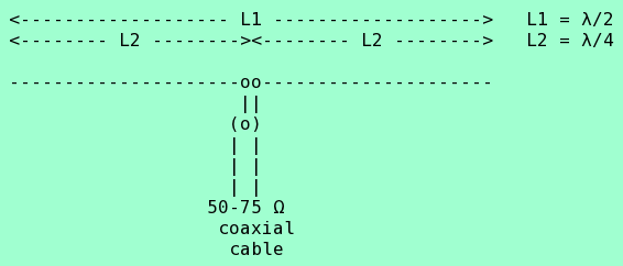
A dipole is normally λ/2 total length.
It's a "doublet", a pair of opposed
quarter-wavelength (λ/4) wires
fed at their center:
With f in MHz:
| Length | Meters | Feet | Inches |
| λ |
300/f
|
984.25/f
|
11811.00/f
|
| λ/2 |
150/f
|
492.13/f
|
5905.51/f
|
| λ/4 |
75/f
|
246.06/f
|
2952.75/f
|
The problem is that these dimensions are far too large at HF for my very limited space:
| Length | 30m / 10.110 MHz | ||
| λ/2 |
14.84m
|
48.68'
|
584.13"
|
| λ/4 |
7.42m
|
24.34'
|
292.06"
|
| Length | 20m / 14.040 MHz | ||
| λ/2 |
10.68m
|
35.05'
|
420.62"
|
| λ/4 |
5.34m
|
17.53'
|
210.31"
|
Squeezing the antennas into 3 meters or 9.84 feet
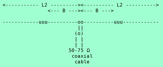
One idea is an inductively loaded antenna. Legs shorter than a quarter-wavelength, with inductors along their length, "uuu" below. The inductive reactance makes the legs electrically equivalent to a quarter-wave wire, at least in theory.
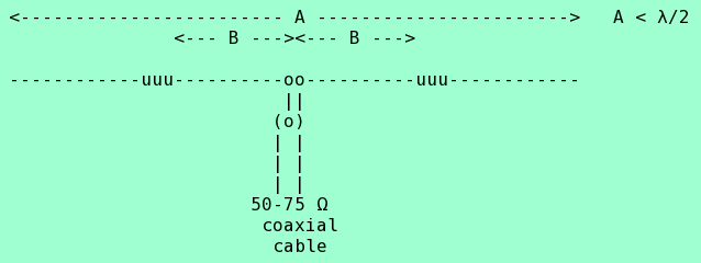
A is some fraction of a half-wave.
If A = 0.2,
then the shortened doublet is 20% the length of a
full-size dipole.
B is some fraction of the length of its leg.
If B = 0.4,
each inductor is 40% of the way from the feed point
to the end of the leg.
Given the size of my balcony, and the availability and relative stablility of 10-foot PVC pipe sections, an overall length of 8-10 feet (2.4 to 3 meters) seemed appropriate.
On the one hand, you want the inductors as far as practical
from the feed point, as the that preserves as much
high-current topology as possible.
But on the other hand, the needed inductance climbs fast
as the inductor point moves toward the end.
A range of 40-60% for B seems reasonable.
| Frequency | A | Total length | ||
10.11 MHz
|
20%
|
2.97m
|
9.74'
|
116.83"
|
14.04 MHz
|
25%
|
2.67m
|
8.76'
|
105.16"
|
As for the inductor positions:
| Frequency | A | B | ||
40%
|
50%
|
60%
|
||
10.11 MHz
|
20%
|
0.59m
|
0.74m
|
0.89m
|
14.04 MHz
|
25%
|
0.53m
|
0.67m
|
0.80m
|
From the nomograph in the ARRL Antenna Book (1988, pp 6-6, 6-7, the "Loaded Antennas" section of Chapter 6, "HF Antennas for Limited Space"), the following approximate inductive reactances are needed:
| A | B | ||
| 40% | 50% | 60% | |
| 20% | 2300jΩ | 2600jΩ | 3200jΩ |
| 25% | 1900jΩ | 2100jΩ | 2600jΩ |
Inductive reactance is:
XL = 2ΠfL
where f is in Hz and L is in Henries (H).
Or, f is in MHz and L is in microHenries (uH).
So:
| MHz | A | B | ||
| 40% | 50% | 60% | ||
| 10.11 MHz | 20% |
2300jΩ 36.2 uH |
2600jΩ 40.9 uH |
3200jΩ 50.4 uH |
| 14.04 MHz | 25% |
1900jΩ 21.5 uH |
2100jΩ 23.8 uH |
2600jΩ 29.5 uH |
The plan is to use PVC pipe for the antenna structure, and to wind the inductors on the pipe itself. Nominal 3/4" PVC pipe has an outside diameter of 1.0625" (27 mm). The coils will be 2-4" (50-100 mm) long.
From the ARRL Handbook,
where d and l are diameter and length,
respectively, in inches, and n the number of turns,
the inductance of a solenoid inductor in microHenries is:
L = (d2n2) / (18d + 40l)
Rearranging to solve for the number of turns:
n = sqrt(L(18d + 40l)/d2)
The plan is to use some insulated wire that can be close-wound at just over 19 turns per inch. So, the only feasible single-layer coils are the 4" coils of 36.2, 29.5, 23.8, and 21.5 uH below:
d = 1.0625 inch
l = 4 inches (max turns: 76)
n = sqrt(159L)
| L | 50.4 uH |
40.9 uH |
36.2 uH |
29.5 uH |
23.8 uH |
21.5 uH |
| n | 90 | 81 | 76 | 68 | 62 | 58 |
d = 1.0625 inch
l = 2 inches (max turns: 38)
n = sqrt(89L)
| L | 50.4 uH |
40.9 uH |
36.2 uH |
29.5 uH |
23.8 uH |
21.5 uH |
n |
67 | 60 | 57 | 51 | 46 | 44 |
d = 1.0625 inch
l = 1 inches (max turns: 19)
n = sqrt(52L)
| L | 50.4 uH |
40.9 uH |
36.2 uH |
29.5 uH |
23.8 uH |
21.5 uH |
n |
51 | 46 | 43 | 39 | 35 | 33 |
So, the best practical designs for my constraints seem to be:
| Frequency | L2 | B | Loading coil, 1.0625" ID, 4" length | |||||
| 10.11 MHz | 20% | 1.49m | 58.4" | 40% | 0.53m | 23.4" | 36.2 uH | 76 turns |
| 14.04 MHz | 25% | 1.34m | 52.6" | 60% | 0.80m | 31.6" | 29.5 uH | 68 turns |
Construction
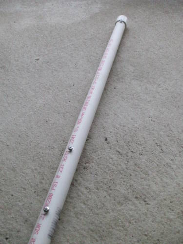
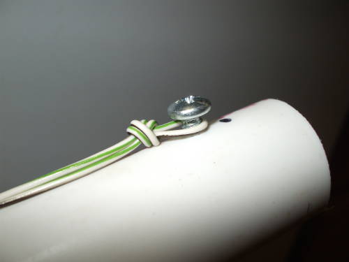
The pipe segments are cut to length, pilot holes drilled, and sheet metal screws inserted.
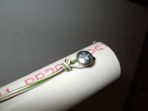
At the far end of the wire you tie a half-hitch in a loop and place that around the outermost screw.
Then tighten the knot by moving the knot itself as close to the screw head as possible.
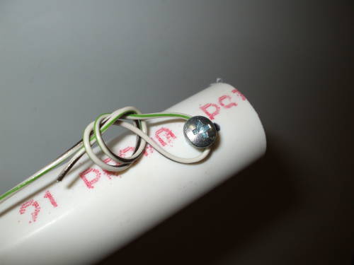
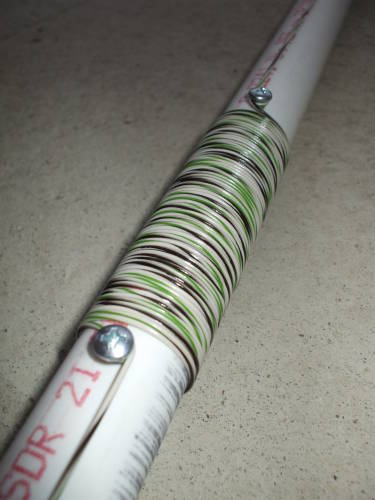
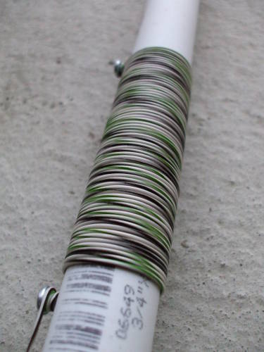
Here is an inductor after winding — 68 turns for the 20m model, 76 turns for 30m.
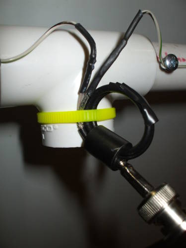
I prepared short pigtail cable left over from an earlier project. This one has RG-174/U miniature coaxial cable. There was just enough cable for two turns through a ferrite "barrel" salvaged from an old computer monitor.
I later wound some electrical tape around the two loops.
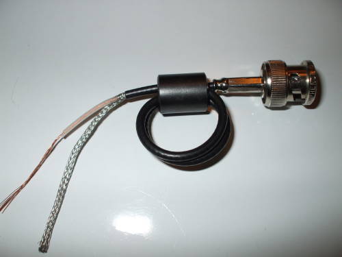
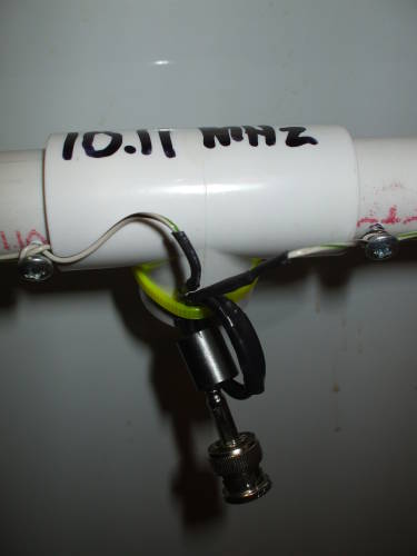
Solder the cable to the center ends of the wires and use a plastic cable tie to fix the feed cable to the center tee.
To fasten the horizontal arms to the tee, I used some clear spray sealant. It's mostly spray solvents, largely acetone, which is all that PVC "adhesive" is anyway.
Pull the joints slightly apart, hit the outer surface of the ends of the pipe with the spray, and re-insert them, twisting them slightly back and forth to more deeply seat the pipes and distribute the solvent.
The Petlowany coil ground plane experiments described by, Jake Groenhof, N0LX might provide some useful components for small HF antennas.
Back to the KC9RG radio page