The J-Pole or Half-Wave End-Fed Zepp Antenna
What is it?
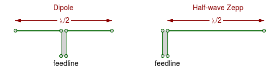
The Half-Wave Zepp is an end-fed half-wave antenna. That is, it is a piece of wire one-half wavelength long with the feedline connected at one end.
The very common dipole antenna is a half-wave wire that is broken at the center for connection to the feedline. Think of the Zepp antenna as a dipole that is fed from one end instead of the center.
Like a dipole, it might be an odd multiple of half wavelengths: λ/2, 3λ/2, 5λ/2, and so on.
Unlike a center-fed dipole, an end-fed antenna has a very high input impedance. That makes sense if you think about it. A dipole has high current at its center but zero at its ends (because there's nowhere for it to go). It has high voltage at its ends, but very low to zero voltage around its center.
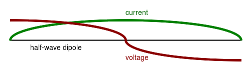
Center-fed: high current but low voltage = low impedance.
End-fed: high voltage but low current = high impedance.
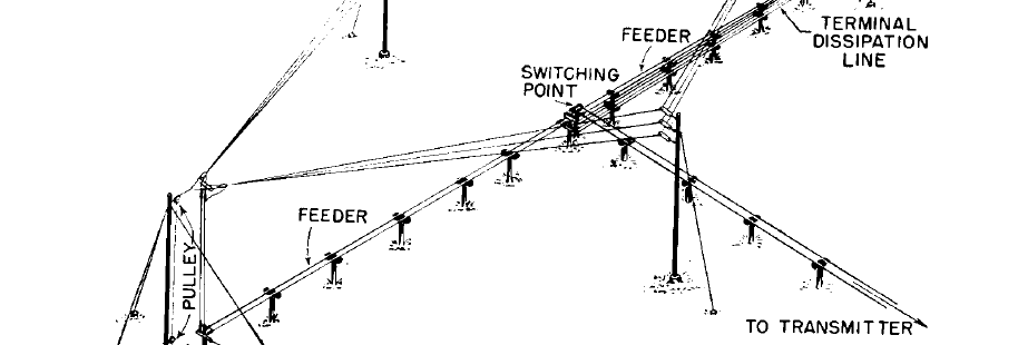
The end-fed antenna's name comes from its first common application. The Zeppelin airships used a resonant antenna consisting of a dangling wire an odd number of half-waves in length.
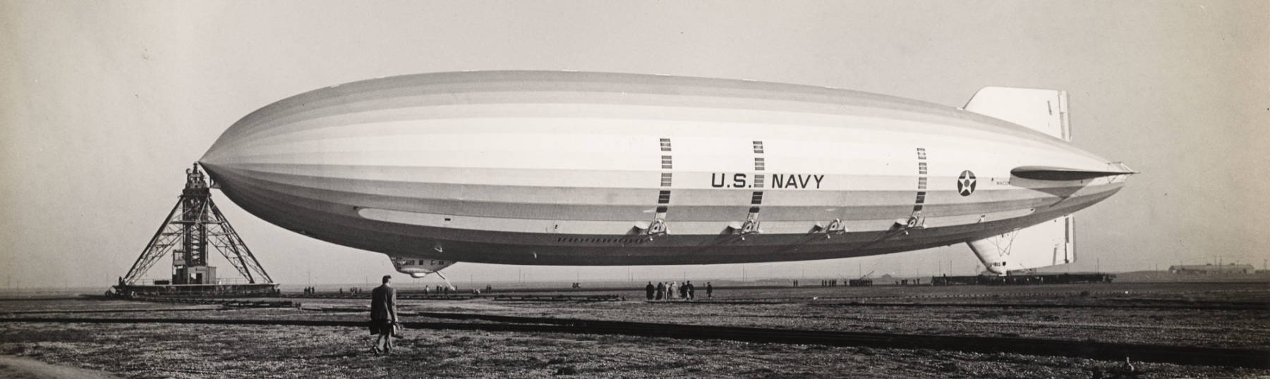
The U.S. Navy airship USS Macon was a 785-foot dirigible. It was damaged, crashed into the Pacific Ocean, and sank in February 1935. Zepp antennas are named for German dirigibles, but they would have been just as useful on anyone's airship.
How do you build a Zepp antenna?
Vertical end-fed half-wave antennas are commonly used on VHF and UHF FM, as they are easy to build and perform well. In that setting they are often called J-pole antennas because of their shape, especially when made from copper pipe.
A copper pipe J-pole is certainly sturdy, but it's even easier to make one from 300Ω twin-lead transmission line. Twin-lead isn't as common as it was when everyone with a television had an antenna, because TV was all terrestrial broadcast. But it's still available at home improvement stores and on-line.
Amazon
ASIN: B003AKA08O
Amazon
ASIN: B06XZ31W3M
The general design for a twin-lead Zepp is a 50Ω coax feedline, a λ/4 matching section, and a λ/2 radiating section. The feedline taps on near the bottom of the matching section.
Feeding the J-Pole
Make an RF choke out of the coax feedline near the feed point. Wind it into at least 3 or 4 turns, maybe a 4-inch diameter loop if you're using RG-58, more like 6-8" if it's RG-8 or RG-213.
If you have torn down an old PC power supply, pass the turns through one or more of the large ferrite cores you salvaged. The precise size and material doesn't matter, you're just making your RF choke more effective than a simple air core.
Tape that loop so it remains a coil.
An RF choke is an inductor whose precise value doesn't matter. We just want enough inductive impedance to block RF currents. In this case, we're making the RF choke out of the shield of the coax. We want the RF energy to travel out the interior of the coax and then flow into the antenna. We don't want RF flowing back down the exterior of the coax, so we form an RF choke. A loop with 3-4 turns should be enough at VHF frequencies. If the turns pass through a ferrite core, the inductance will be a little higher, and the RF choke will be a little more effective.
Building the J-Pole
The most commonly used practical design for a twin-lead J-pole is as follows. L1 is the λ/2 radiating section. L2 is up the λ/4 matching section, shorted at the bottom (shown at left here). L3 is the distance from the short to the feed point.
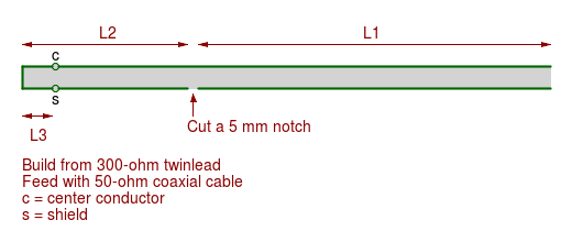
Punch a small hole through the dielectric near the far end to suspend the antenna from a non-conductive cord. You can place the entire antenna inside a 0.5" PVC pipe.
The speed of light is almost exactly 300 million meters per second, so the familiar formulas are:
| 300/f = λ |
| 300/λ = f |
|
f = frequency in MHz λ = wavelength in meters |
The precise speed is 299,792,458 meters per second. Our approximation of 300 million is within 0.07%. Don't worry about it, there's no way we will cut wire or tubing with that precision!
Velocity Factor
Light travels at 300 million meters per second in a vacuum, the ideal "free space". It travels a little slower through air, glass, and other transparent media, by a factor indicated by the media's refractive index.
Dielectric constants of many materialsSimilarly, electrical signals travel slower along an electrical conductor a little slower than light travels through a vacuum, depending on the dielectric constant of the surrounding material. The velocity factor is the fraction of the speed of light at which electrical signals move. If the velocity factor of a cable is 90%, then signals move through it at 90% of the speed of light in a vacuum.
When you build an HF wire dipole antenna, we usually use a velocity factor of 0.96 or 96%. That is, calculate the theoretical half-wavelength and then multiply it by 0.96.
There's a bit of a "fudge factor" in there. We use the same velocity factor regardless of whether the wire is insulated or not, and with what material, and we also disregard wire gauge. But, we seldom build a single-frequency antenna. We want to cover a range of frequencies and nothing can be ideal across the band. 0.96 is plenty accurate for our purposes.
When you compare the cross-section of typical twin-lead to that of insulated wire, the twin-lead has much more surrounding insulation relative to the conductor diameter. That increases the dielectric constant, slowing down the signals more.
When you look up velocity factor for twin-lead, you see numbers from 0.8 to 0.86. That's for difference mode, where the transmission line is being used as intended, with equal and opposite currents in the two conductors. For current in just one conductor, it's more like 0.9.
Idea for a technical project: Measure the velocity factor for the twin-lead you have.
Twin-lead's velocity factor isn't unusually low. The velocity factor for Ethernet cable is even lower. Ethernet is twisted pair, really a collection of four twisted pair transmission lines within an outer jacket. The twisting makes the distance along the wires greater than the overall end-to-end cable length. On top of that, the insulation on the individual wires, plus that of adjacent wire pairs, plus the outer jacket, all contribute to the dielectric constant for a wire pair, further slowing signals. Cat-5e and Cat-6A twisted pair have a velocity factor of 0.64-0.65, while Cat-7 is 0.74-0.79.
Dimensions for a Twin-lead J-Pole
I am using 0.9 for the velocity factor for the λ/2 radiating section, and 0.83 for the λ/4 matching section. So, while L1 and L2 have electrical lengths of λ/2 and λ/4, respectively, L2 is physically less than half of L1.
| 300Ω Twin-Lead J-Pole | ||||
| Dimensions, where f = frequency in MHz | ||||
| Units | meters | cm | feet | inches |
| L1 | 135/f |
13500/f |
443/f |
5315/f |
| L2 | 62.25/f |
6225/f |
204.2/f |
2451/f |
| L3 | 6.119/f |
611.9/f |
20.07/f |
240.9/f |
J-Pole Antennas Beyond VHF and UHF?
The feed point attachment will be the limiting factor as you move higher in frequency. An end-fed Zepp could be a good antenna at 1 GHz and above, especially since greater lengths like 3λ/2 and 5λ/2 become practical. But it would be difficult to get the J-pole type feed close enough to resonant at those short wavelengths.
I would be willing to try to make one for 440 MHz FM. The quarter-wave matching section would be about 17 cm or 6.7 inches, tapped about 1.6 cm or 5/8 inch from the shorted end (and see the last table for precise dimensions for your design frequency). FM is nearly an "all or nothing" modulation, either full-quieting signal or not very useful, and digital modes are even more so. A J-pole for the local 440 MHz FM repeater sounds like a reasonable plan. Make it out of large-diameter stiff copper wire, and measure carefully.
But I wouldn't try making one for 902 or 1296 MHz! And really, why not just make a quarter-wave whip with 3 or 4 radials for a local FM repeater?
Going the other direction, you could certainly make a twin-lead-based "J-pole type" antenna for the HF bands. Make the quarter-wave matching section from 300Ω twin-lead, and the half-wave radiator from plain old wire. Just realize that it's going to be a horizontal wire on 30m and longer frequencies!
However, your end-fed half-wave for HF probably isn't
going to use tapped twin-lead as a matching section.
You might use a tuner near the radio
and a long ladder-line feed line to the antenna.
Or, there might be coax to a matching transformer at
the feed point.
For discussions and examples see, for example:
AA5TB (1)
AA5TB (2)
HA5KDR
M0UKD
QRP clubs and small companies sell small
end-fed half-wave tuner kits that work great.
Among others, see:
QRP Guys
SOTABEAMS
ILERTENNA
QRP HamRadio Kits
Amazon
ASIN: B001G4462M
Amazon
ASIN: B001AH5BJ2
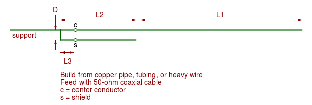
Dimensions for a Pipe or Wire J-Pole
The traditional J-pole antenna is made from copper pipe. For higher bands it could be copper tubing, or even large-diameter wire.
The twin-lead version is nice for its small size and weight, and how you can roll it up for travel or slide it into a PVC pipe and stand that in the corner of the room.
The copper pipe version is nice because you can use small stainless steel hose clamps at the feed point and then adjust the feed position.
Amazon
ASIN: B076Q7ZK19
Amazon
ASIN: B01MAVV8WQ
Use a tee to add a support piece below the hot side of the matching section. Attach that to a handy vertical support.
This table uses a velocity factor of 0.96 throughout, as these dimensions are for wires or tubing sections.
| Copper Pipe or Wire J-Pole | ||||
| Dimensions, where f = frequency in MHz | ||||
| Units | meters | cm | feet | inches |
| L1 | 144/f |
14400/f |
472.4/f |
5669/f |
| L2 | 72/f |
7200/f |
236.2/f |
2835/f |
| L3 | 7.077/f |
707.7/f |
23.22/f |
278.6/f |
| D | 6.7/f |
670/f |
21.98/f |
263.8/f |
Amazon
ASIN: B00O4D1CUG
Amazon
ASIN: B0019CQL60
Close the ends of the sections with pipe caps. Make the measurements to the ends of the pipe caps, so you will need to cut the pipe sections just a little short. Also, account for the length added by the elbow and tee. Distance D is between inner sides, not center to center.
Amazon
ASIN: B00AZXYA76
Amazon
ASIN: B01MEDL6BZ
The simple impedance bridge described by Harry Lythall, SM0VPO, could be very useful when experimenting with antennas.
Other J-Pole pages
Glynn E "Buck" Rogers K4ABT J-Pole page
Basic article on the twin-lead J-pole
K4ABT's J-pole calculator for arbitrary frequency