Rhombic Antennas
Classic Rhombic Antenna Designs for UHF & Microwave
Rhombic antennas were the ultimate antenna design back in the Golden Age of Wireless. However, building one required a large tract of land and a lot of telephone poles, because they have dimensions several times the wavelength, and back then the wavelengths in use were tens of meters and longer.
These were the main antennas for point to point links through the end of World War II. Since then, log-periodic and curtain arrays have become more popular.
There isn't a lot of design and practical information available. I suspect that is because not many people needed the information, a form of "If you have to ask then you don't need to know", and practical installations varied somewhat based on the available real estate.
But now, with UHF and microwave bands using wavelengths of less than a meter, rhombics are of practical size and might be easier to build than the antennas commonly used on those bands.
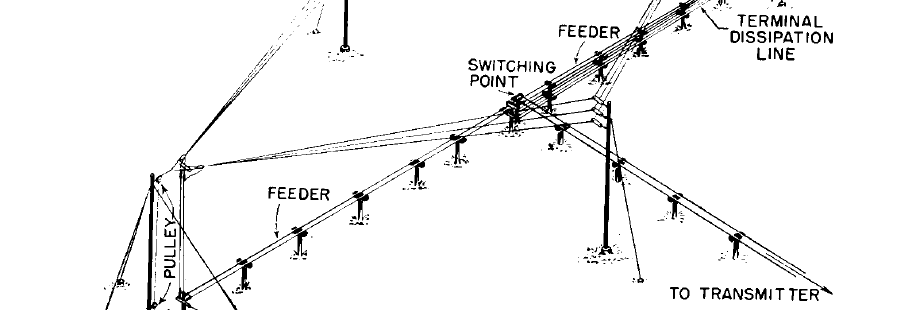
Below is Figure 3.77 from Edmund Laport's textbook Radio Antenna Engineering, published in 1952 and now out of copyright and freely available, scanned and processed into PDF by Dave Platt, AE6EO.
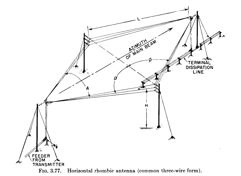
As you can see, telephone poles are used to suspend the corners of the rhombus, and this could occupy a lot of real estate when each leg is a multiple of a wavelength on the order of 20 to 160 meters. This example uses a set of three wires for increased bandwidth.
The antenna is fed with a balanced feedline at lower left apex in the image. The "terminal dissipation line" is basically a non-inductive resistor joining the lines at the far apex. The antenna is unidirectional in the direction away from the feed point when terminated this way with a resistance of 600 to 800 Ω,
As for the details, well, it depends. The gain and impedance depend on the length L and diameter of the legs and the angles φ and A defining the overall shape and dimensions. The ARRL Handbook for 1936 briefly described this antenna design using single wires for each leg and suggesting the choices of dimensions and shapes in the below table. This shape is said to provide about a 2:1 range of frequencies.
| L | φ |
| 1λ | 30° |
| 2λ | 50° |
| 3λ | 57° |
| 4λ | 62° |
| 5λ | 65° |
| 6λ | 67° |
| 7λ | 68° |
| 8λ | 69° |
Laport said in his book:
"From a circuital standpoint the rhombic antenna,
when terminated at the far end in its characteristic
impedance Z0, has an input impedance
which is predominantly resistive and equal
approximately to Z0.
For the three-wire type, this value is on the order
of 600 ohms, which matches well with ordinary
two-wire balanced feeders.
After construction the input impedance should be
measured and the feeder impedance matched to
the measured value.
[....]
When used for receiving, the terminal resistance for a
unidirectional system is usually installed directly
at the far end in the form of a non-inductive
resistor.
[....]
For medium- and high-power transmitting purposes, the
terminal resistance is almost always a balanced
lossy line of high dissipation capacity."
There hasn't been a lot of information about rhombic antennas in either the professional or amateur radio publications. QST and QEX magazines carried, with one exception, just the following articles about rhombic construction since 1940 (plus a few about historical antenna installations, like the Voice of America transmitter site north of Cincinnati, or the W6AM antenna farm). Going backwards in time:
"Achieving Near Perfection with the Imperfect Rhombic", Joel Hallas, W1ZR, QST, Nov 2004, pg 28-32. He used uneven legs of 164, 73, 100, and 142 feet (clockwise from the feed point) for operation on 10 through 21 MHz. At the lowest frequency and longest wavelength, those are lengths of: 1.68λ, 0.75λ, 1.03λ, and 1.46λ, so this is a relatively small rhombic as they generally go, at least for the 10.1 MHz or 30m band. There are lots of EZNEC simulations of theoretical radiation patterns, although the practical antenna is in a fairly random setting running through trees above irregular ground.
"A Practical Guide to the Design of Rhombic Aerials", Domenic Mallozi, N1DM, QEX, Dec 1988, pg 14 This appears to have been just correspondance on the topic.
"The Invisible Rhombic", J Gregg Stephenson W2OBX/W1DGC, QST, Nov 1977, pp 38-39. He used legs of 250' (3.6λ at the intended frequency of 14 MHz) with apex angles at the feed and end points of about 50 degrees, and a height of 30-45'. His was non-terminated and fed with 600Ω open-wire feed line.
"Five-in-One Rhombic Array", Zack Scott, ZL3GG, QST, Oct 1974, pg 33. Basically just a description of four rhombics with legs of 275' each pointing NE, SE, SW, and NW, inside a roughly square rhombic with legs of 625' each.
"The Half-Rhombic Antenna", John Mullaney, W4HGU, QST, Jan 1946, pp 28-31. The idea here was to scale it to VHF operation, vertically oriented, with just one half of the antenna above a conductive ground plane.
"Plain Talk about Rhombic Antennas",
Ross Hull and C.C. Rodimon, QST, Nov 1936,
pp 28-29, 74, 101, 102, 106.
This is a well-written and amusing article, with
difficulties caused by poison ivy and other
undergrowth, the inconveniently spring-like
behavior of Copperweld wire, and friendly rivalry
as to reported signal quality.
Its opening sentence shows that this article
goes back to the start of the Rhombic story:
"Four years ago, shortly after Bruce announced
the development of the rhombic antenna,
we put up an experimental antenna of this
type with the idea of working Asia."
The larger of the two rhombics it discusses has
four equal sides about 2.5λ long at 14 MHz.
Then there is the dual rhomboid antenna. This seems to have been first described in "Dual Rhombic for VHF-UHF", Bill Parker, W8DMR, 73 magazine, Aug 1977. Dayton Johnson, W0OZI, built an antenna for the 1296 MHz (23 cm) band based on Parker's design. Johnson's specific design was then described in the column "The World Above 50 MHz", Emil Pocock, W3EP, QST, March 1997, pp 89-90.
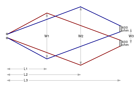
The design consists of two rhomboids with legs of uneven length, overlaid as mirror images about a central axis. Each is terminated with a 600Ω non-inductive resistor for a net feed resistance of 300Ω, a nice match to commonly available (for now!) television twin-lead.
| in | cm | λ | |
| W1 | 30.5 | 77.5 | 3.348 |
| W2 | 42.5 | 108.0 | 4.666 |
| W3 | 12.0 | 30.5 | 1.318 |
| L1 | 27.5 | 69.9 | 3.007 |
| L2 | 50.0 | 127.0 | 5.487 |
| L3 | 77.0 | 195.6 | 8.451 |
The QST article gave dimensions in inches for a 1296 MHz design. Here are those dimensions plus both centimeters (for construction) and wavelengths (for scaling to other frequencies):
The two short legs and two long legs are not precisely equal.
The lengths of the segments in wavelengths at 1296.1 MHz are:
3.45λ
5.91λ
5.96λ
3.40λ
The result for 1296 MHz is a fairly simple antenna with non-critical dimensions and a claimed gain of about 20 dB over a dipole!
The overall size is quite manageable, about 196×108 cm.
It could be fed with 300Ω balanced line leading to a half-wave balun built from 75Ω coax, transforming the 300Ω balanced to 75Ω unbalanced. Cheap 75Ω coaxial cable could be used all the way to the transceiver or transverter, or a quarter-wave matching transformer used to convert that to 50Ω.