SVGA Connector Pinouts
SVGA Cables
SVGA stands for Super Video Graphics Array, although you almost never see it spelled out. It has been a very common standard for video display cabling.
IBM published the VGA standard in 1987, and SVGA was meant to be an extention to that. However, although SVGA cards began appearing that same year, in 1987, VESA did not define a standard for programming SVGA modes until 1989, and SVGA never became an official standard.
This page describes SVGA cables. See the HDMI cable page for descriptions and pinouts for HDMI cables.
A VGA/SVGA chipset performs digital computations, but the digital results are used to generate entirely analog signals for the red, green, and blue components of the image.
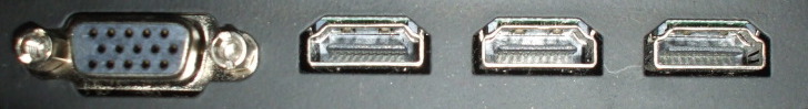
SVGA devices use the same connector as VGA, variously called DE-15, HD-15 and 15-pin D-subminiature.
The connectors and cables carry analog component video signals: Red, Green, Blue, Horizontal sync, and Vertical sync. They also carry VESA Display Data Channel data.
VESA DDC allows the display to communicate its supported display modes to the video adapter, and also allow the computer to adjust brightness and contrast. Four pins were previously defined to be pulled to ground by resistors to encode up to seven monitor classes.
DDC redefined two of those for an I2C serial link interface. Many KVM (keyboard-video-mouse) switches and video extenders and splitters mishandle the DDC communication. One solution may be to disable video plug and play features in the operating system or the X11 driver configuration. A physical solution is to remove pin 12. See, for example, the explanations for X11 on Linux/Unix and for Windows Vista.
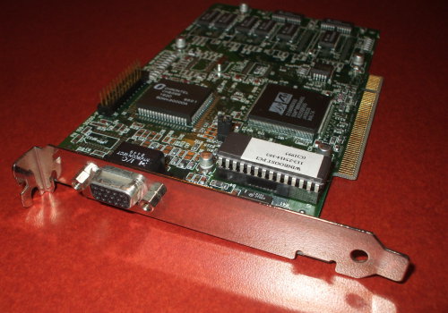
SVGA output connector on an ATI Mach64 PCI bus video adaptor.
| SVGA pinout looking into computer connector with wide edge at top. | ||||||||||
|
Pin 5 Ground |
Pin 4 reserved |
Pin 3 Blue video |
Pin 2 Green video |
Pin 1 Red video |
||||||
|
Pin 10 Ground |
Pin 9 +5 V DC |
Pin 8 Blue return |
Pin 7 Green return |
Pin 6 Red return |
||||||
|
Pin 15 DDC I2C clock |
Pin 14 Vertical sync |
Pin 13 Horizontal sync |
Pin 12 DDC I2C data |
Pin 11 reserved |
||||||