HF QRP with KC9RG
Transceivers
40 meters —
7038.5—7039.5 kHz
Norcal SMK-1
650 milliwatts transmit power
0.178 μV MDS receive sensitivity
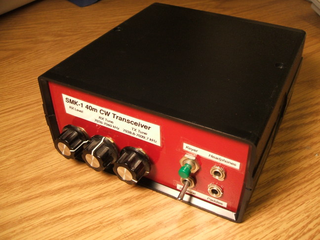
I had just finished building the Norcal SMK-1 40m QRP transceiver kit when a consulting client was throwing away a whole box of unused plastic cases... I just needed to shear some sheet aluminum to make a bunch of appropriately sized panels, and find some long 4-40 screws to hold the case halves together.
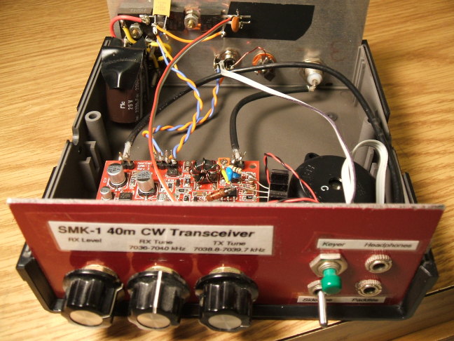
As you can see with the top cover removed, this medium to small transceiver case (5.25"x5"x2.25" or 133x127x57 mm) is mostly empty space! That's just fine with me, it's still small and I have plenty of room to work on it.
I created a power circuit on the interior of the rear panel. A bridge rectifier, 7809 regulator, and capacitors it allow to be fed with 10 to 15 volts AC or DC. Just give it electricity and it runs.
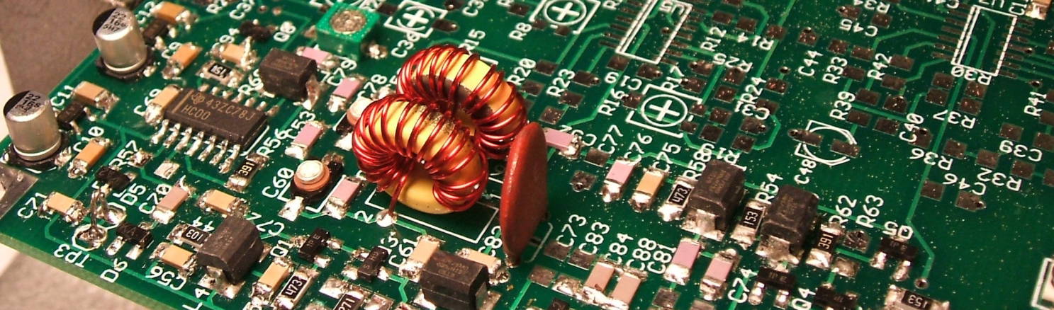
This was my first surface-mount transceiver project. But it's not too hard with the relatively large 1206 surface-mount devices (0.12 x 0.06 inches).
The Norcal QRP club's point in making this kit was to provide an SMT (surface-mount technology) construction trainer.
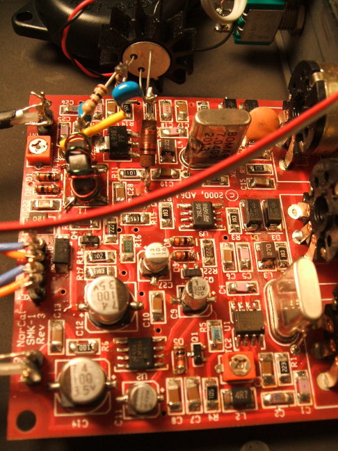
The transceiver circuit board mounts to the front panel by the three pots controlling the receive gain and the receive and transmit frequency. I did the "high-power modification" to boost power from about 360 mW to 650 mW. So, the final amplifier transistor is up off the board with a finned heat sink.
I added a TiCK Morse code keyer chip. It's also a surface-mount chip on its own small board attached to the interior of the front panel. A surplus piezo-electric sounder provides external audio feedback on keying, if it is switched in. See it just beyond the power transistor in the two pictures above, or at the lower left corner in the image at left here. It isn't really needed given the way the QSK full break-in works on this design.
For TiCK and NorCal keyer chips see Jackson Harbor Press.
Best DX (so far!) has been WA3BKD, operating from a houseboat on the Ohio River near Weirton, West Virginia. That's about 540 km from here in north-central Indiana. Most of the way across Indiana and all the way across Ohio. Now bad for 650 milliwatts to a quarterwave monopole thrown off the balcony and across the top of a small tree.
The SMK-1 was a kit sold by the Norcal QRP Club. It's no longer offered, but for details see the American QRP Club's page. For a good presentation of the construction, see WB8RCR's page.
30 meters —
10100—10150 kHz
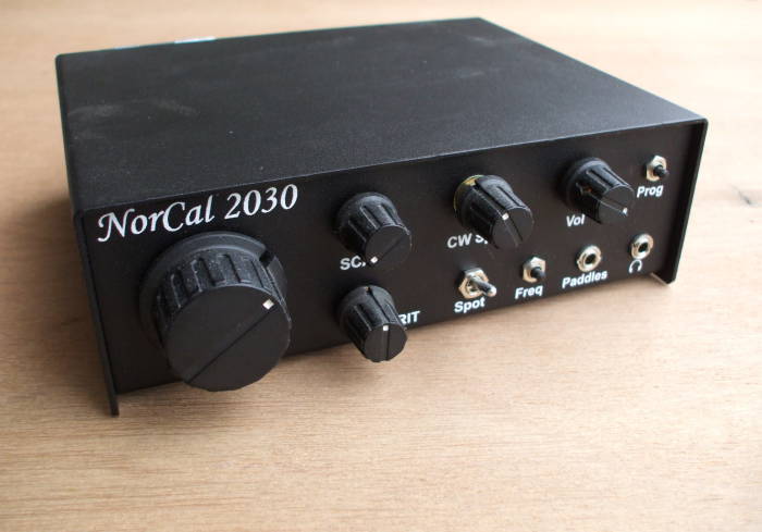
NorCal NC2030
4.0 watts transmit power
0.181 μV MDS receive sensitivity
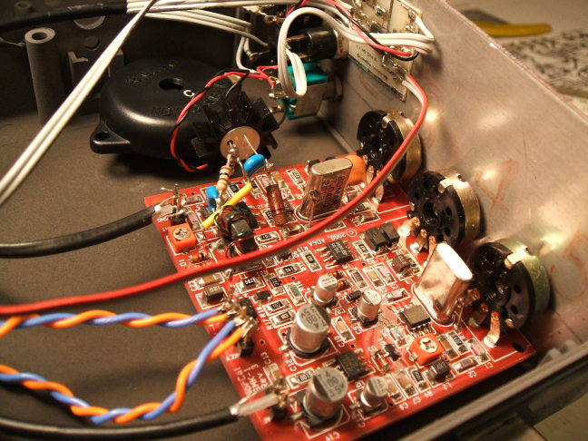
The NorCal 2030 is a nice design by Dan Tayloe, N7VE. It's an I/Q quadrature direct conversion transceiver. It's complicated enough to get its own page.
It can be built for either the 20m or 30m band. I chose to build mine for 30m as I didn't have a QRP radio for that band!
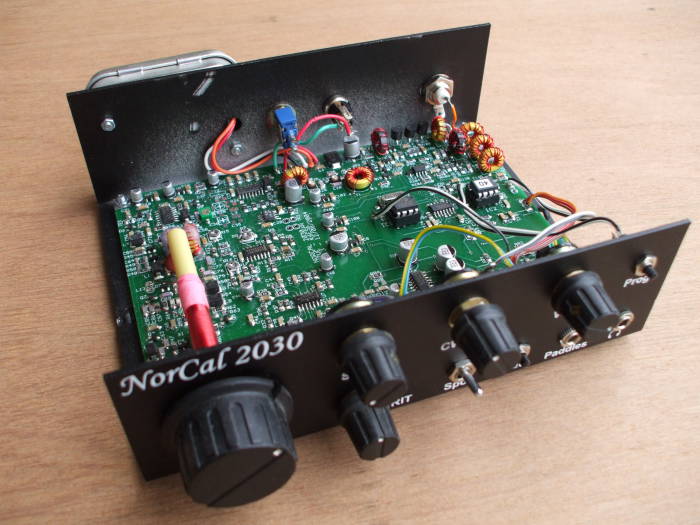
It uses almost entirely surface mount technology. The US $0.01 coin (19.05 mm diameter, 1.55 mm thick) provides scale.
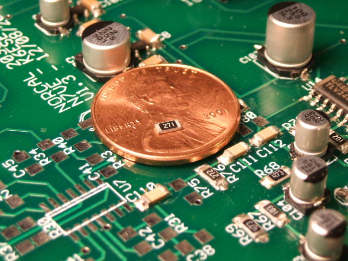
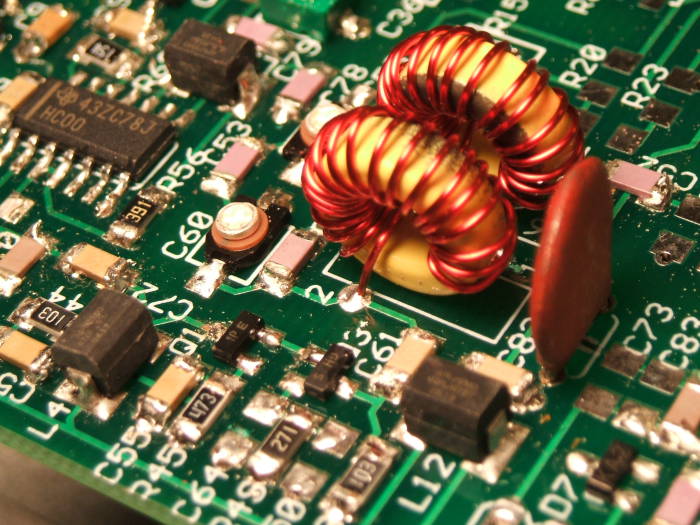
There are a few toroids, and the long solenoidal inductor of the permiability-tuned oscillator, plus two 8-pin DIP chips. However, the bulk of the work is surface mount. The hardest parts for me were the 3-terminal transistors and dual diode packages with their tiny tabs.
The NC2030 was a much bigger project than the other radios shown here, so it has its own page.
20 meters —
14100—14110 kHz
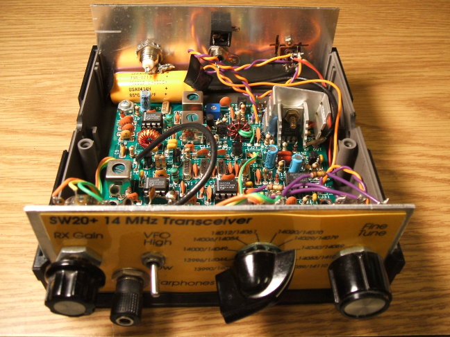
Small Wonder Labs SW20+
1.6 watts transmit power
0.251 μV MDS receive sensitivity
I then built the SW20+ 20m transceiver. Yes, I put everything in those cases.
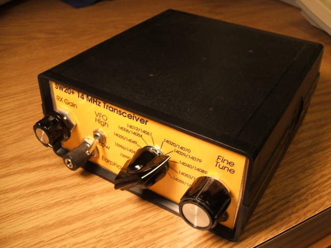
The front panel is just a Postscript file printed out and photocopied onto colored cardstock. There's more inside than in the SMK-1.
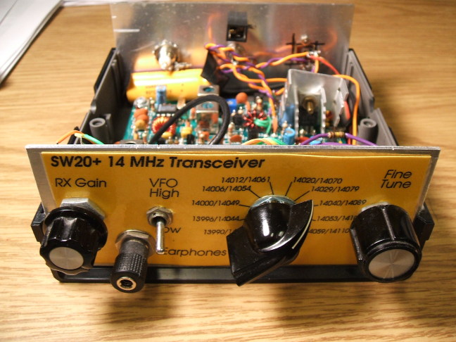
I added a larger heat sink to the final amplifier, and added a power filter capacitor.
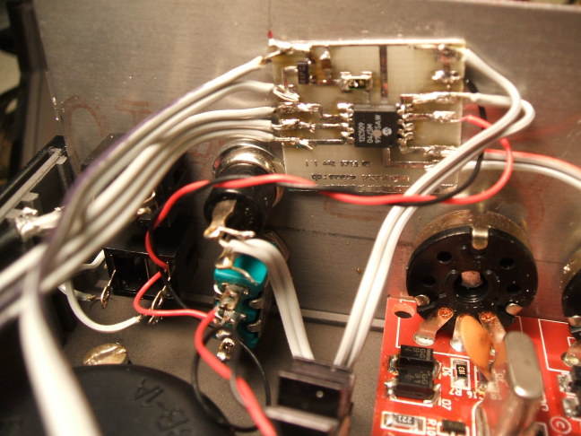
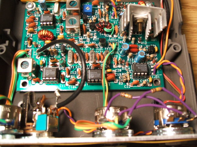
Toward the left side of the second image below you see a switch (blue-green), RG-174 coax (black backwards "C" shape), and the two tuning pots, joined by resistors with purple wire insulation pulled over their leads. These make up the frequency coverage modification described below.
Best DX (so far!) was S5VK, in Slovenia, in a contest. Wow, those Slovenians have good receivers and good hearing....
The SW+ series of transceivers were designed and sold as kits
by Dave Benson, K1SWL.
Modifying the SW20+ for expanded frequency coverage:
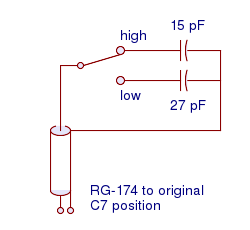
First, replace C8 with a 47 pF NPO/C0G capacitor.
Second, replace C7 with a short piece of RG-174 coax running to a SPDT switch selecting between two capacitors, as shown in this picture
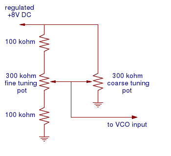
Third, replace the VCO tuning potentiometer. The original design uses a 50-100 kohm potentiometer from regulated +8V to ground, with the VCO input taken from the wiper. Replace that with the circuit shown here.
My result was a range of 13990 - 14059 kHz in the low range, and 14039 - 14110 in the high range, with fine tuning available across the total frequency range.
Keys and Paddles
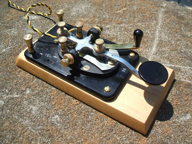
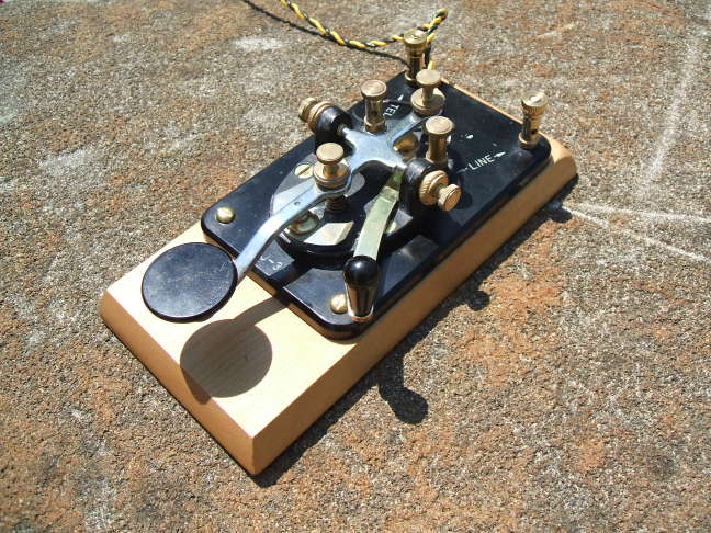
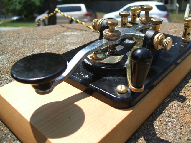
Straight Key
This military surplus J-38 has been cleaned up and put back into operation. It's fully adjustable for travel and tension.
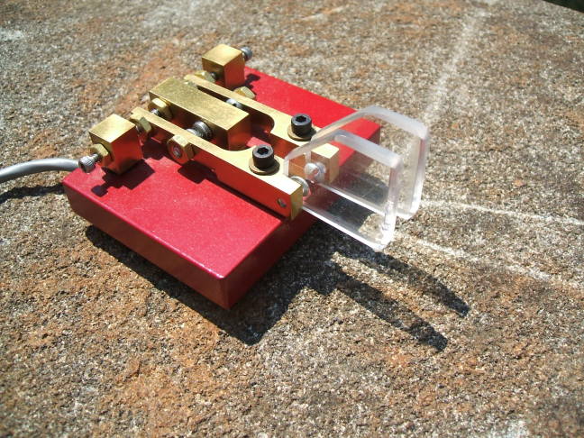
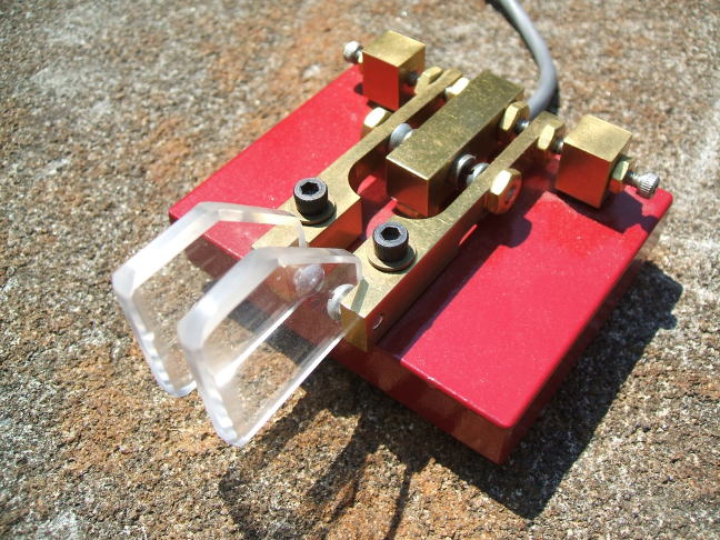
Paddle
Norcal also put out a mechanical construction kit. The heavy steel base was ready to go, but the brass and plexiglass parts all took some finishing work. It's adjustable for travel, and the tension is magnetic.
I had some minor issues with contact oxidation on both of these, and tried burnishing the contacts and then rubbing on some Ox-Gard conductive grease. Not enough to call it a layer, more that I rubbed it onto the surface and wiped it off, leaving only a very thin film. That seems to have fixed the problem.
Morse Code tables
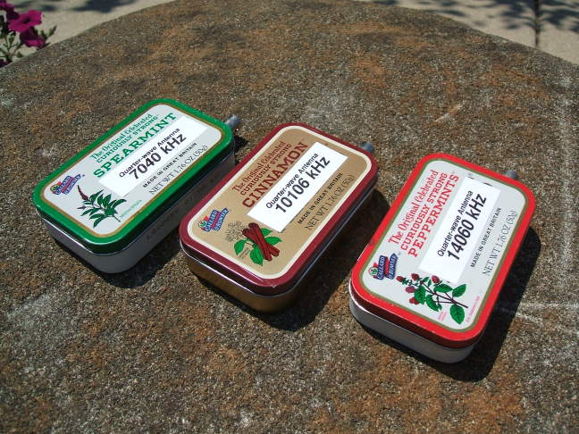
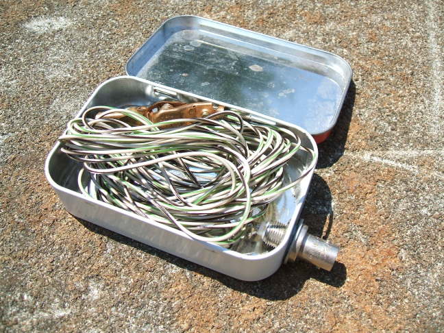
Curiously Strong Minty-Fresh Antennas
Cut a hole in an Altoids tin with a Dremel tool and install a BNC jack so the lid can still close. A screw in the bottom floor holds a wire lug connected to about 2 meters of wire with an alligator clip. The BNC center conductor goes to a quarter-wavelength of wire, the far end of which is tied in a small loop around a large nut. Attach the alligator clip to some handy ground or counterpoise. Throw the other end into a tree or over some shrubbery. Here are separate models for 7040, 10106, and 14060 kHz, flavor-coded by frequency.
I/Q Quadrature Direct-Conversion Transceivers
This can make for a very high performance HF system. Rick Campbell, KK7B, has written a series of articles in QST magazine starting in the early 1990s, see below for a bibliography.
More recently, Dan Tayloe, N7VE, has designed some systems that do I/Q quadrature conversion using switching rather than traditional mixers. See the NC2030 design above for an example.
Also see some articles describing the technology as an "H-mode mixer", named after the circuit topology. Sergio Cartoceti, IK4AUY, wrote an article in QEX magazine.
Siniša Tasić, YU1LM, has also used it in some interesting designs that combine sample-and-hold quadrature modulation and demodulation with software-defined radio technology. See his web page for the details.
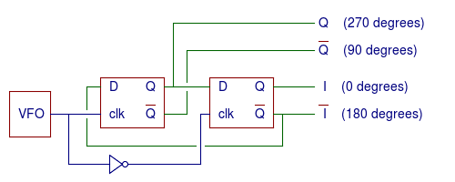
Generating I/Q Quadrature Local Oscillator Signals
Here's a way of doing it digitally. Use a VFO running at 2 times the desired LO frequency, and use high-speed D flip-flops to generate the quadrature signals. The resulting four LO signals will be square waves, which are in fact preferred assuming you do it right and provide:
1: A low-pass filter on the mixer RF port
2: Broadband 50-ohm termination on all mixer ports
This approach is used in the designs by Dan Tayloe, N7VE. See both "A Low-noise, High-performance Zero IF Quadrature Detector/Preamplifier" in RF Design magazine, and his NC2030 transceiver design.
| VFO | 1 | 0 | 1 | 0 | 1 | 0 | 1 | 0 | 1 | 0 | 1 | 0 | 1 | 0 | 1 |
| I | ··· | 1 | 0 | 1 | 0 | 1 | 0 | 1 | |||||||
| I | ··· | 0 | 1 | 0 | 1 | 0 | 1 | 0 | |||||||
| Q | 1 | 0 | 1 | 0 | 1 | 0 | 1 | ··· | |||||||
| Q | 0 | 1 | 0 | 1 | 0 | 1 | 0 | ··· | |||||||
A bibliography on the topic includes:
- "New Low-Power Single Sideband Circuits", Philips Semiconductors Application Note AN1981
- "RF Phase Shifters for Phasing-Type SSB Rigs", Byron Blanchard N1EKV, QEX, Jan/Feb 1998, pp 34-39.
- "The Bedford Receiver: A New Approach", Rodney Green VK6KRG, QEX, Sep/Oct 1999, pp 9-23.
- "Notes on 'Ideal' Commutating Mixers", Doug Smith KF6DX, QEX, Nov/Dec 1999, pp 52-54.
- reply to above, QEX, Mar/Apr 2001, pp 61-62.
- "Reducing IMD in High-Level Mixers", John Stephensen KD6OZH, QEX, May/Jun 2001, pp 45-50.
- "A High-Performance Single-Signal Direct-Conversion Receiver with DSP Filtering", Rob Frohne KL7NA, QST, Apr 1998
- "Direct-Conversion Radio Transceivers for Digital Communications", Asad Abidi, IEEE Journal of Solid-State Circuits, vol 30, no 12, Dec 1995, pp 1399-1410
-
Rick Campbell, KK7B,
all from QST magazine:
- High-Performance Direct-Conversion Receivers, Aug 1992 pp 19-28
-
High-Performance Single-Signal
Direct-Conversion Receivers,
Jan 1993 pp 32-40.
Errata: Apr 1993 pg 75 - A Multimode Phasing Exciter for 1 to 500 MHz, Apr 1993 pp 27-31
- Single-Conversion Microwave SSB/CW Transceivers, May 1993 pp 29-34
- A Small High-Performance CW Transceiver, Nov 1995 pp 41-46
- Direct-Conversion Receiver Noise Figure, Feb 1996 pp 82-84
- A Binaural I-Q Receiver, Mar 1999 pp 44-48
- The MicroR2 — An Easy to Build "Single Signal" SSB or CW Receiver, Oct 2006 pp 28-32
- The MicroT2 — A Compact Single-Band SSB Transmitter, Dec 2006 pp 28-33
Links
Operating and references
HF Gear
Steve Weber, KD1JV — — Some extremely impressive kits and designs!
Hendricks QRP Kits — — Even more impressive kits for transceivers, tuners, and test gear!
Kanga US — Sells TiCK keyers — 8-pin microcontroller keyers with memory.
Dan's Small Parts and Kits — – No minimum with very low shipping.
Parts And Kits — — No minimum order with flat $4.50 shipping per order.
American QRP Club — A quarterly journal and some very nice kits.
Northern California QRP Club — They're certainly wide open to membership outside northern CA, encouraging low-power HF operation everywhere. From time to time they have put out some very nice kits.
Wilderness Radio — Simple Superheterodyne Transceiver kit.