How to Build Your Own Oscilloscope Probes
Building Your Own Oscilloscope Probes
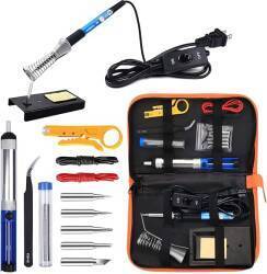
Amazon B06XZ31W3M
Sure, you could buy oscilloscope probes from Amazon
or eBay.
But where's the fun in that?
This project shows you how to build your own
test probes for oscilloscopes or other instruments
using household items.
The only "electronic parts" needed are a piece of 50-75Ω
coaxial cable with a BNC connector at one end and two small
resistors.
You will also need an alligator clip and a short piece
of insulated wire, both of those commonly found in hardware
stores.
Design
Many instruments can use simple wire leads to connect a small pointed test probe to the instrument input. However, oscilloscopes and other instruments used with high frequency signals need more complex probes in order to avoid distoring the very signal you are trying to measure.
You will likely have problems if you directly connect an oscilloscope to a circuit under test using a coaxial cable with clips on the end. This is what might be called a 1× probe. If you were only measuring constant DC voltages, perhaps measuring battery voltages, a 1× probe would be fine. But in that situation you would use a voltmeter. The complexity, size, and expense of an oscilloscope are only justified because you need to measure or visualize a rapidly time-varying signal.
Oscilloscopes typically have input impedances on the order of 1MΩ. Meanwhile, 50-75Ω coax typically has a capacitance of about 100 pF per meter. That means a very low impedance at radio frequencies. That low impedance significantly loads the circuit under test, and that in turn distorts the measurement.
Something like a 10:1 resistive divider probe circuit is commonly used to avoid these problems. Here is a simple 10× attenuating probe design that presents a load of about 5 megohms to the circuit under test.
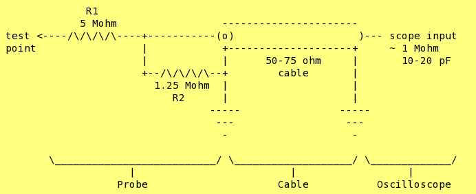
Why is this a 10X probe?
R2 in parallel with the scope input impendance is:
1/(1/1.25 + 1/1) = 0.5555...
And so the ratio is:
(5 + 0.5555...)/0.5555.... = 10
The 1.25 MΩ resistor at R2 is a series combination of 1 MΩ and 250 kΩ resistors. Dealing with junkbox resistors (wait until you see the probe body!), the imprecision of your resistors and scope input impedance come into play. You could worry about the precision, or just call it "close enough"
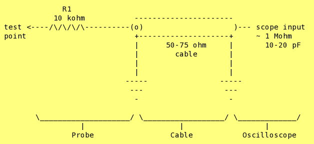
Alternatively, here is a 1X probe with a lower but still reasonably high impedance:
For more on probe circuits, see these pages:
- Probing High-Speed Digital Designs, published in Electronic Design in 1997.
- Basics of High Voltage Probe Design
- DC to 1 GHz Probe Construction Plans
- Probing for Answers from Pomona Electronics
Construction
Here's how I built my own oscilloscope probes.
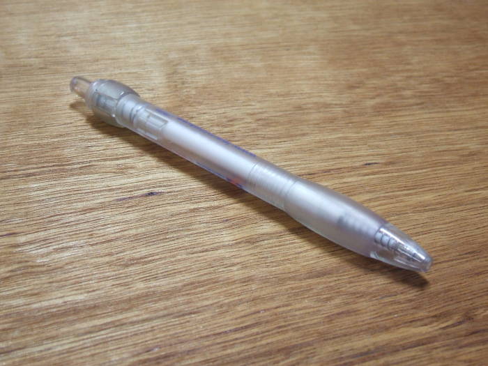
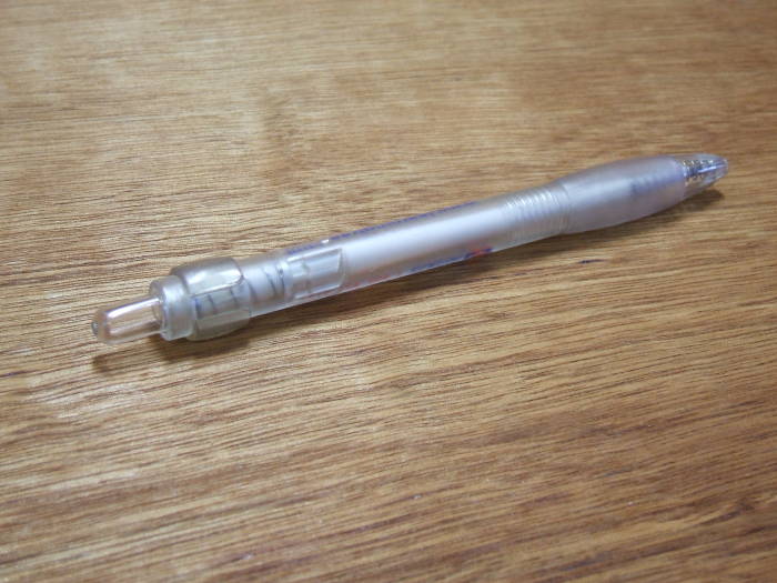
I had some promotional pens with an intriguing design. The business end has a rubber-coated bulge making them pleasant to use as pens.
So why wouldn't they make pleasant oscilloscope probes?
It's important that the pen body is entirely plastic and rubber. Many pens have a metal cone at their tip, or at least a metallic coating on plastic.
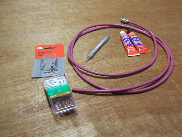
Here is the complete bill of materials:
- The pen
- A 2-meter piece of coaxial test cable with a BNC connector on one end
- Epoxy adhesive
- One alligator clip
- Copper-plated nail — 0.75" (20mm) long, packed as "weather-stripping nail".
- 1 MΩ and 5 MΩ resistors
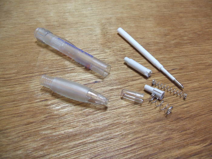
Start by disassembling the pen.
Keep the pen main body and large body tip, the two large translucent pieces in this design.
Discard the remainder.
That is, unless you have a use for those pieces...
Slip the upper barrel onto the cable, oriented so the free cable end is toward where the pen point used to be.
Put another way, the cable running to the BNC connector exits from the end where the push button used to be. You will hold the pen as if you are writing when you use the probe.
Strip back the outer jacket.
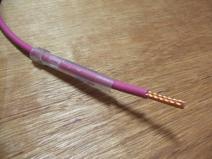
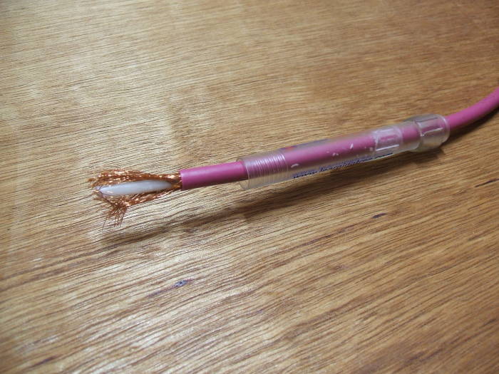
"Comb" the braid to open the braid without cutting or breaking the individual wires.
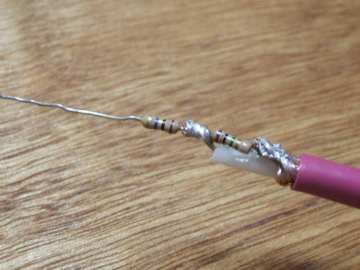
Twist the braid around the lead of a 1 MΩ resistor, and solder the lead into place.
See the initial discussion about using a series combination of 1 MΩ and 250 kΩ for a more precise 10X ratio. I am using a single resistor in this version.
This is R2 in the schematic above.
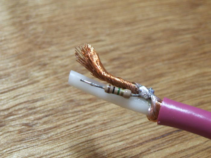
Trim the braid. Remember that this must fit into the pen tip, so you need to be careful in the above step of connecting the resistor R2 and this step of trimming the braid.
Connect a 5 MΩ resistor as R1 to the R2 resistor. Again, I am using just a single resistor as R2.
Strip back the cable dielectric even with the far end of the R2 resistor.
Twist the center conductor around the R1-R2 junction, and solder this new connection. This is 75-Ω coax with a stranded center conductor, making this step easier.
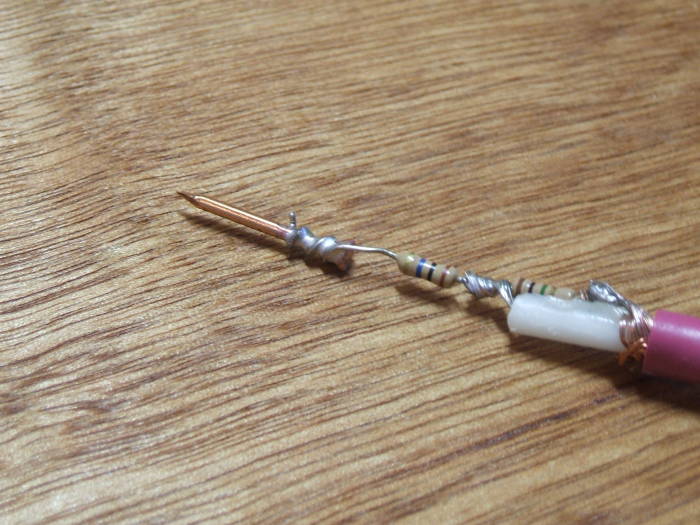
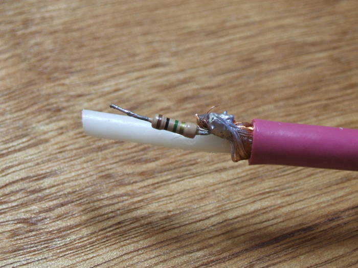
Wind the far lead of the R1 resistor around the nail shaft near its head, and solder that junction.
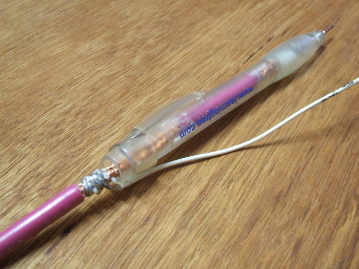
Here is another view of things so far.
I used the pen tip as a guide to cut the lengths of the center conductor and resistor leads to appropriate lengths. The secton picture below shows the pen tip slid onto this assembly, but I simply held it next to the end of the cable to gauge appropriate lengths.

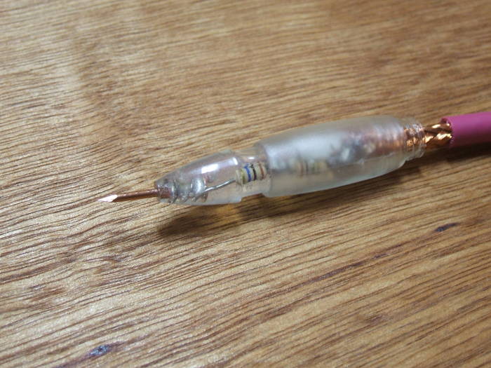
Mix the two-part epoxy and stuff it into the pen tip. The tricky part was getting the viscous epoxy into the tip.
My solution was to "wind" as much epoxy as possible around the large toothpick I used to mix it, and let it drip into the pen tip. After several iterations of that, use the toothpick to work the epoxy into the tip.
In this picture I have pushed the probe (nail) into and through the tip, and wiped the epoxy off the probe.
Slide the pen body into place and mark the cable jacket at the upper end of the pen body. Then slide the pen body back up the cable.
Cut away a short section of jacket just above where you marked the position of the uppend end of the pen body. This will allow a connection for a ground clip wire.
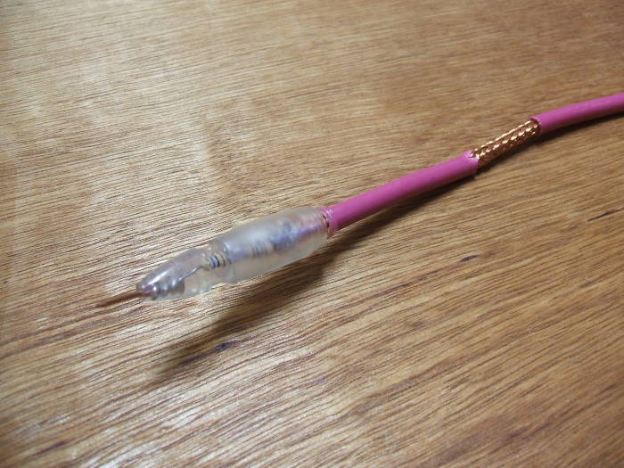
Slide the pen body back into place, and screw it into the pen tip.
Solder a length of teflon-insulated wire onto the braid just above the end of the pen body.
Solder an alligator clip to that newly added ground wire.
Mix another small puddle of epoxy and work it into the upper end of the pen body, between the pen body and the cable.
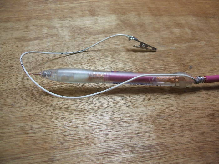
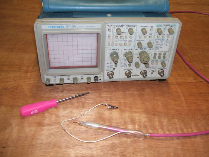
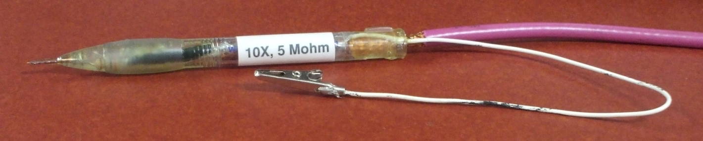
The probe is ready to use!
Click here to see my page about repairing that Tektronix 2445A oscilloscope.