Repairing a Tektronix 2445A oscilloscope
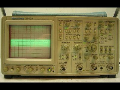
The Tektronix 2445A
I bought a Tektronix 2445A oscilloscope from eBay. It was a very good deal for a 4-channel 150 MHz oscilloscope. Maybe too good a deal, or so it seemed for a while...
The seller used the usual eBay boilerplate disclaimer for electronic gear — they had turned it on, no smoke came out, it lit up, but they "were unable to test further". It was guaranteed not to be "DOA" ("Dead On Arrival"), which probably means only that smoke shouldn't appear and it should "light up" when you turn it on, and nothing more.
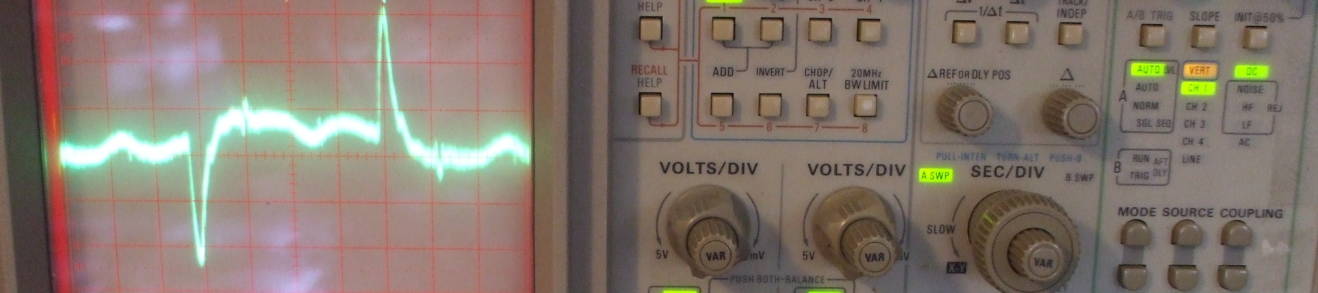
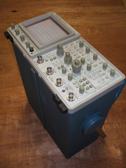
The problem was that the scope would not focus! The very best, with the focus control turned to the end of its range, was as pictured. The trace was at least 1.5 cm wide, and the on-screen indication of vertical scale and horizontal timing was nothing but pale green smudges instead of readable characters.
I had not placed a bid on the item until after I had
found a PDF file of a service manual.
Places to find service manuals include
bitsavers.vt100.net
and
bitsavers.org.
Those were discovered by
asking Google
for something like:
			tektronix 2445
				"service manual" filetype:pdf
So, I had a service manual and
now it was time to get to work...
The alignment procedure includes setting the trace focus as sharply as possible, and then using the astigmatism control (a small screwdriver-set pot below the display) to further refine the setting. Yes, the astigmatism control had some effect, but it seemed as if I needed another 90-180 degrees of rotation on the focus control to get the job done.
| YOU SHOULD NOT READ BEYOND THIS POINT. |
| ABOVE ALL, YOU SHOULD NOT DO WHAT I DID. |
| IT IS VERY VERY DANGEROUS AND YOUR LAWYER WOULD NOT APPROVE. |
| BUT IT DID FIX MY OSCILLOSCOPE.... |
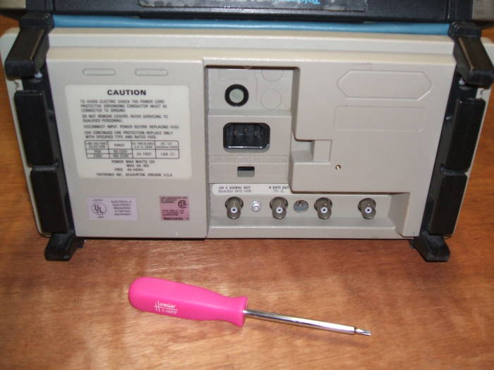
Removing the case
I needed some Torx drivers — T-20, T-15, and T-10 got me through the entire project.
I removed the six Torx head screws and
then removed the rear panel.
Before starting.
The rear panel has been removed.
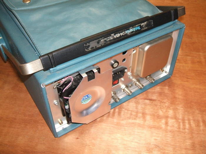
I tipped the unit up onto its back end, and then very carefully lifted the oscilloscope out of its case.
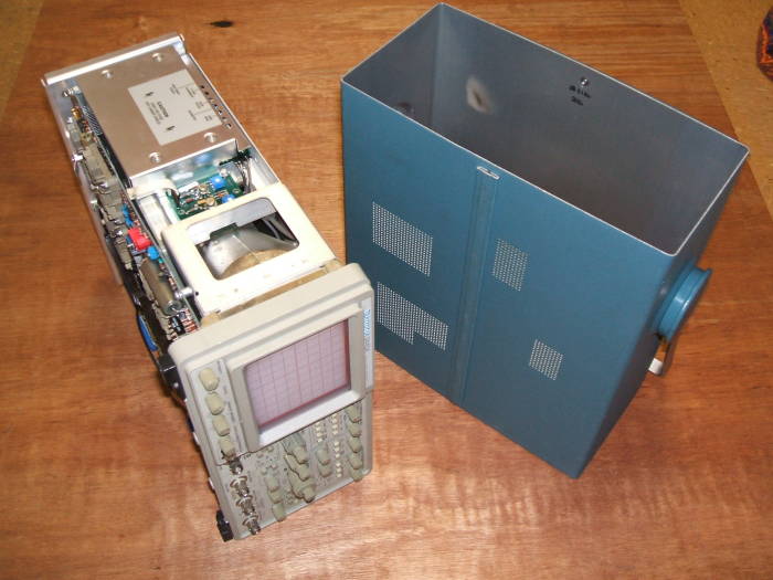
Removed from the case.
Stood up but with rear cover removed.
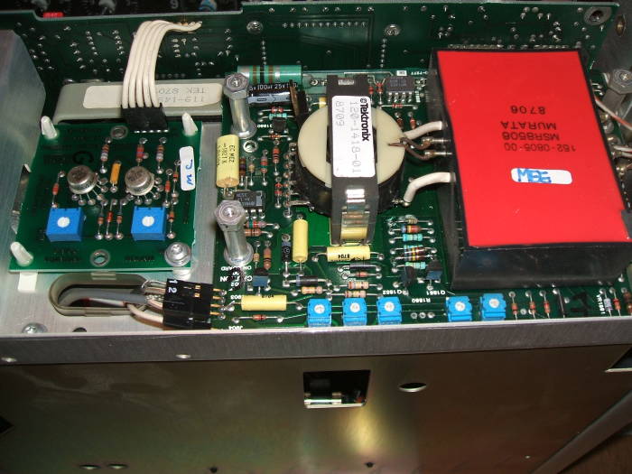
I was looking for the high voltage power supply. An aluminum cover panel must be removed to expose it. This requires two sizes of Torx drivers.
The high voltage power supply is at the top here. In the first picture it is still hidden underneath the aluminum cover.
In the second picture, I have removed four T-10 screws and one T-15 screw and then removed that cover.
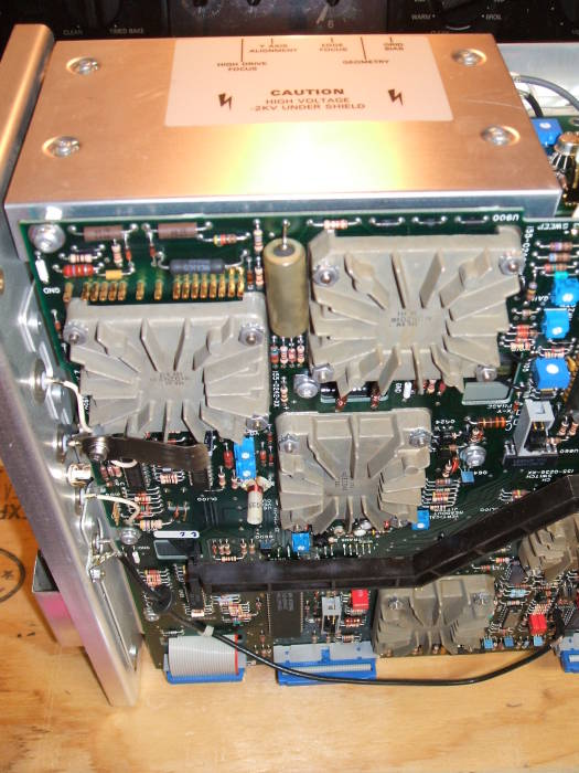
High voltage power supply at top.
High voltage power supply exposed.
MaxTek U400 module failure
See those grey modules with heat sink fins in the above pictures? Those are hybrid modules. Some of them are very prone to failure. Here's how someone described the symptoms to me:
After some research with my 2445B I found the failure ??, however I am not able to fix it. The vertical amp (U600) is a funny piece of hybrid-ceramic-module (TEK 165 2393 00) see picture attached. According to the schematic there was a potentiometer (R639) for the VERTICAL-CENTER! I set it to the -5V at one end. Luckily it the move in right direction,but not enough! To get it more negative a 2.7K ohm resistor connected to -15V and the U600 (Pin39) moved the picture then to the center now. (-5.7V) Another problem appeared suddenly, the gain changes if you move with vertical-position over the screen!? I believe that the hybrid (U600) is some how defective and I have here no means to test it.
And then in later messages:
Finally in the end the U400 was defective! Insider told me that this Hybrid U400 (155-0236-00) is defective in 90% of all cases!? (85 €) And so it was!
It seems that there is problem with the MaxTek Version.
(155-0236-00 or -09).
https://forum.tek.com/viewtopic.php?t=138544
Tracing the focus control voltage
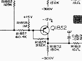
Tracing the control voltage from the wiper on the focus control into the high voltage power supply board, I found that the control had no easily measureable effect on the output of focus amplifier transistor Q1852. The output focus voltage was fixed at approximately -300 V DC. Further testing showed that the precision 332kΩ resistor R1854 had become an open circuit and now was a fairly precise infinite impedance....
With R1854 opened — effectively removed — Q1852 was no longer correctly biased. And so that transistor was not controlling the output voltage as designed. Here you see the circuit biasing Q1852, click on the picture or here for the full page from the service manual.
Replacing R1854
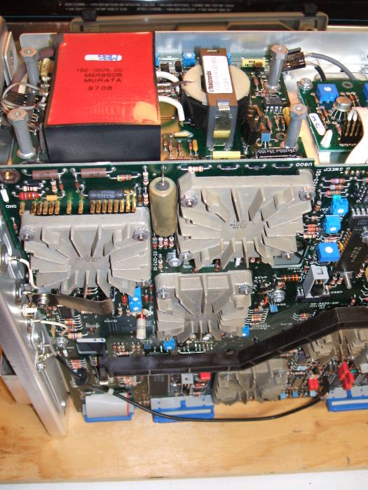
Above is the view from the opposite side. R1854 is in the row of resistors between the white-topped transformer and the red potted HV circuitry.
I did not have a 332kΩ resistor handy, but I did have two 680kΩ resistors that I could stack in parallel. The original quarter-watt resistor was asked to dissipate about 0.19W continuously, and this was probably the cause of its failure. Since I would be using two quarter-watt resistors in parallel, I should have much more thermal leeway.
R1854 is just left of the bottom left corner of the red potted high voltage circuitry.
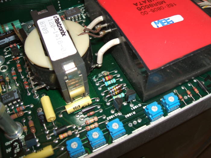
R1854 is near the center, above the center blue potentiometer.
You can see my repair here — the pair of 680kΩ resistors is stacked vertically in the original R1854 position. The repair sequence was:
- Cut one lead of R1854 as close to the resistor body as possible, using small diagonal cutters.
- Bend the resistor body upright, bending the remaining lead in the process.
- Heat and remove the cut lead.
- Heat the other lead and remove the resistor body.
- Use the soldering iron and solder sucker to open the holes.
- Make very certain that no solder blobs have gone anywhere, on the top of the board or below it.
- Bend and trim the leads of one 680kΩ resistor, and solder it into place.
- Bend and trim the leads of the other 680kΩ resistor, and solder it into place piggyback fashion.
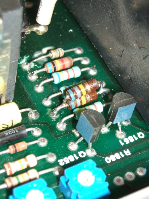
Closer view of stacked 680kΩ resistors.
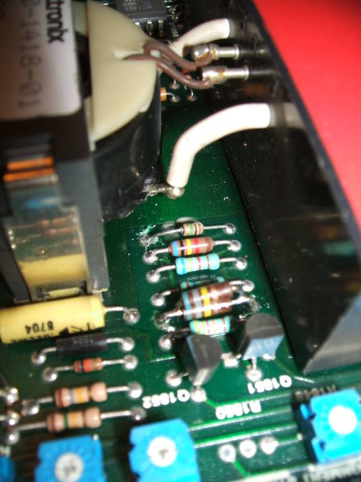
The replacement for R1854 is at the bottom of the row of resistors.
And that fixed it! A friend later told me that he had had a nearly identical experience on a different piece of test gear. A precision resistor had failed to an open circuit and disabled the instrument's display. It isn't very clear why the design uses a precision resistance (in a circuit with multiple potentiometers!) instead of a more rugged device.
A different problem — can you help?
Vinny, N2LWN, bassist10@comcast.net, found my page through Google and sent me the following:
Hi Bob, I got one of these on ebay too. It seemed to work fine until I stopped using it for a couple of years and the lithium battery holding the setups wound down. Now for some reason the darn thing needs 20 minutes before I can see the error code on the confidence test. Fails test 5 code 44 trigger too positive main board failure.
After I escape this function via menu button everything seems to work fine. DMM display is clear, trace and readout clear in focus etc., but as time goes by it shuts itself off (2 hrs.). After it cools down a bit it seems to take even longer to produce the readouts, they appear shrunken and take longer to expand to normal size. I have no clue what might be causing this and the service manual is not clear about any specific adjustment/repair.
Does anyone have any idea about how to fix that? If so, please contact Vinny, and also copy me so I can add it to this page!
Someone else's corrosion-caused problem and fix
This is from Jeremy Linton, and it sounds like the fix to at least part of Vinny's problem described above....
I picked up a Tek 2445 from ebay back in 1999 or so. Its been great for intermittent use.
Anyway, last night I was monitoring a circuit and went to change channel 1 from DC to AC, when it clicked and the scale illumination light went out, all the indicator lights went out and the buttons stopped responding. The trace was still running though.
Power cycling yielded a test 05 fail 22 message. Out with the service manual and the bad news, it looked like the trigger control IC (hybrid) had suddenly become very sensitive to temperature. The test would pass if the device was off for a few minutes. Once warned up, it would act up by "crashing" at which point the buttons would stop working.
So, I pulled it expecting to find some dry ancient heat sink compound, thinking I could keep it cool enough to work while I found a replacement. Instead, I discovered the terminals were corroded to the point where I'm amazed it was working at all. A little 600 grit sandpaper and Q-tips with isopropyl alcohol got them shining again. Seems the problem is solved, the scope ran the test 5 loop for an hour or so without a failure.
I figured if that IC was corroded, the others might not be so good either. I pulled the preamps and a couple of the other IC's, cleaned them and put the whole thing back together. It appears that fixed some of the signal noise I was blaming on the cheap probes I've been using.
I'm not saying this is what is causing the 05/44 but I'm betting this is pretty common. Mine has been kept in pretty controlled AC for the last 10 years and before that was a school lab tool, meaning it probably sat in AC for the first 15 years of its life too. 25+ years is a long time to corrode. It's probably a matter of time before enough capacitance builds up on the terminals to cause a malfunction somewhere when the device heats/cools and the terminals move a little on the pads. So, this fix was just another variant on the old reseat the IC solution, but I thought it worth mentioning anyway.
Yet another problem and fix — TEST 05 FAIL 44
Someone posted to an electronics forum:
I have a Tektronix 2445B scope that shows "Test 05 Fail 44"
on startup "Press A/B Trig To Clear" which when pressed
all seems well.
What is this error message all about?
Will it prove fatal and can it be fixed if so how?
The conclusion — "Press A/B Trig to Clear" comes up when any of the power-up tests fails. Routine Test #05 is done on the main board, code #44 means that the trigger level is just a little too high.
Here is the sequence of power-on self tests and their meaning, from Chapter 6 of the Service Manual.
|
Test Number |
Routine Name |
Error Code |
Error Code Meaning |
| 01 | Interrupt Request | 01 | Interrupt request is missing or has wrong period. |
| 02 | Switch Stuck |
01 02 08 10 28 30 44 48 50 61 62 64 68 70 |
Trigger COUPLING up Trigger COUPLING down CH 1 Coupling down CH 1 Coupling up CH 2 Coupling down CH 2 Coupling up Δt ΔV Trigger SLOPE Trigger SOURCE down Trigger SOURCE up Trigger MODE down Trigger MODE up A/B TRIG select |
| 03 | Readout Board |
01 02 |
Shift register failure Readout RAM failure |
| 04 | EAROM |
X1 X8 1X |
Read parity error (bit 0 set) Bad read after write (bit 3 set) Bad checksum (bit 4 set) |
| 05 | Main Board |
01 X2 X4 2X 4X |
AUTO LVL failed to trigger Negative level not negative enough Negative level too negative Positive level not positive enough Positive level too positive |
As someone suggested, failure in the voltage test (05 XX) indicates that the voltages are outside the specified ranges. Check the power supply voltages at the empty 14 pin DIP socket near the sequencer chip, as in the service manual. If a voltage is low, suspect the electrolytic capacitors on the power supply.
Then there was speculation on the longevity of the unit — Tektronix said that it was built for 2,000 hours of operation. As for finding the number of hours of operation so far, see Appendix A of the Operator's Manual. A simplified version is:
-
Enter the Diagnostic Monitor mode:
- Press and hold ΔV and Δt simultaneously
- Press Trigger Slope while holding down ΔV and Δt
DIAGNSTIC. PUSH A/B TRIG TO EXIT
- Press the upper and lower Trigger MODE buttons to sequence through the TEST and EXER routines.
- Press the upper Trigger COUPLING button to execute a selected test.
- Exit a test with the lower Trigger COUPLING button.
- Exit Diagnostic Monitor mode and return to normal operating by pressing A/B TRIG.
As for the tests, EXER 05 displays operating time
and power cycles:
> HRS ON nnnn OFF/ON CYCLES mmmm
where nnnn is the accumulated number of operating
hours, and mmmm is the accumulated number of
power on/off cycles.
Also search the Tektronix Forum
Surface-mount technology (SMT) construction — the NC2030 QRP HF transceiver
Back to the KC9RG radio page
Back to the Technical How-To page