
TCP/IP Networking Resources
Getting Started
Networking has its own language. On top of that, there are a lot of acronyms. If you can't speak and understand the language, you won't get anywhere.
Networking used to be an exotic technical area that only specialists saw. But today most everyone is on the Internet. Learn the names, and things will get easier.
The OSI Model
Yes, this is an academic model that always appears when networking comes up. But it's useful!
Here, in written form, is how I explain in about 15 minutes all you need to know about networking for an introductory cybersecurity course. The OSI model, or at least the important parts of it, helps people to quickly understand the different tasks that networking must perform simultaneously.
| Layer | Device making decisions at this layer | |
| 7 6 5 |
Application Jobs software programs do |
ALG, AV, Spam filter, DLP, WAF, etc |
| 4 | Transport UDP: Messages to numbered ports TCP: Connections to numbered ports |
Firewall |
| 3 | Network Relay packets hop by hop to anywhere by IP address: [netid|hostid] |
Router |
| 2 | Data Link Send frames to HW/MAC addresses |
Switch |
| 1 | Physical Send and receive 0 vs 1 bits |
Repeater (link) or hub (star) |
Understanding the Protocols
The protocols are defined by documents called RFCs. Those documents can be found at rfc-editor.org and tools.ietf.org/html.
However, those documents include far more than you probably want to know. See my quick overview if you just want a reminder of the headers.
Amazon 013608530X
Amazon 0321336313
Get reference texts, but save money by buying older editions. You need to understand IP routing, ICMP rules, TCP handshaking, and so on, and those things haven't changed for decades. Here are some of the books on my shelf:
Internetworking with TCP/IP, Volume 1, Douglas Comer, Prentice Hall. This is a very readable description of the major components (and many of the minor ones) of the TCP/IP internetworking protocol suite. Comer's book is the best place to start.
TCP/IP Illustrated, Volume 1, W. Richard Stevens, Addison-Wesley. A bit tough for an introduction, but a good one to follow Comer's book with lots more details. Comer's book is readable, this is more like an encyclopedia.
Managing IP Networks with Cisco Routers, Scott M. Ballew, O'Reilly and Associates. Good advice on IP routing with Cisco.
Interconnections: Bridges and Routers, Radia Perlman, Addison-Wesley. Loads of details on routing algorithms and protocols.
These organizations design protocols, identify standards, and define and dissemenate The Truth:
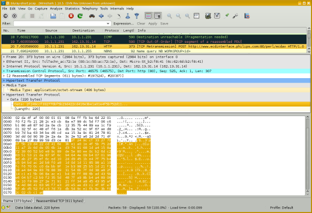
Network Monitors, or Packet Sniffing
NetworkMonitoring
The Wireshark software package can capture and display network traffic.
You might refer to this as "network monitoring", or "packet capture", or "protocol analysis". You might be troubleshooting, or you might be stealing passwords or sensitive data. Protocol analyzers are dangerously powerful tools!
Amazon 180323167X
Amazon 1118918215
Operating System Details
Every operating system has its own command-line interface to check and set network parameters. Linux, Windows, macOS, Cisco, they all do it their own way. Learn the command-line networking tools.
IP configuration on Raspberry Pi, Ubuntu, and Debian
How to break in, initialize, and configure a Cisco router
How to program Cisco Catalyst and 3com 3000 switches
Cisco Catalyst 2900 XL Ethernet switch disassembly and repair
How to harden the TCP/IP stack of Linux or any other UNIX-like operating systems
Physical / Data Link Layers
Network and Telecommunication Cables
Fiber Atlantic's Submarine Cable Map
Undersea Cables
Submarine Cable Map
Cisco Catalyst 2900 XL Ethernet switch
disassembly and repair
WLAN link specifications
WAN link specifications
Ethernet MAC address manufacturer codes
Wired, mobile,
and Wi-Fi speeds
world-wide: Ooma infographic
Many marine vessels now have satellite and a fully functioning network online. Many boat factories that build Sportfishing Boats for sale install their own network on board and are able to control all of the ship's functions right from a cell phone or tablet.
Cisco Router Simulators

Typical racks of network equipment: switches, routers, and WAN interfaces.
Ethernet Infrastructure
Modern switched networks are built in a multi-tier architecture. It may be as simple as spine switches at the core and leaf switches for the host connections.
A three-tier architecture uses core, distribution (or aggregation), and access switches. The core switches at, well, the core of your network, distribution switches in data centers, and access switches for host connections.
A top-of-rack or TOR model has an access switch in each rack. Not necessarily at the top! All the servers in that rack connect to the TOR switch. It then connects to a distribution switch for a row of racks, which then connects to a core switch. If the inter-switch connections are fibre, the architecture is somewhat "future-proofed" or "upgrade-proofed" — if you upgrade the TOR access switches, it's a simple replacement.
An end-of-rack or EOR model connects all the servers in all the racks in that row directly to a distribution switch at the end of the row. The advantage is that there is one less switch in the end-to-end connection, and a little less latency. The disadvantage is that the cabling is much more difficult to manage.
Ethernet 5-4-3 rule (the IEEE way)
The rule was needed in the days of 10BASE5 and 10BASE2 bus topologies built from coaxial cable, as the Ethernet standard required that a signal reach every part of the network within a specified time:
- There can only be a maximum of five LAN segments,
- connected via four repeaters,
- and only three may have user connections.
Modern switched Ethernet LANs are exempt from the 5-4-3 rule because switches have buffers to temporarily store frames and all nodes can access a switched Ethernet LAN simultaneously.
Network Layer — IP
IP addresses and subnetsI have a page that aims to be a "just enough" explanation of IP addresses, netmasks, and subnets.
CIDR and VLSMClassless Inter-Domain Routing and Variable-Length Subnet Masks
Another page introduces CIDR and VLSM.
My pages are enough to get you started.
To go deeper into subnet design, VLSM, CIDR, and so on, find and read this 76-page paper by a 3com staff member:
Understanding IP Addressing:Everything You Ever Wanted To Know
VLAN Technology
VLANVLAN or Virtual LAN technology is one of those things that you don't have to use, but once you see what it provides, you will want to.
IP Address Assignment Authorities
IANAThe Internet Assigned Numbers Authority handles global coordination of the DNS root servers and IP address allocation. Then organizations divide up the world by continents.
North and South America — ARIN Latin America and Caribbean — LACNIC Asia and Pacific — APNIC Europe — RIPE Africa — AfriNIC

A rack of Cisco 3600 and 2600 routers forwarding packets based on their destination IP addresses.
Oracle Internet Intelligence Global map showing current disruptions and potential disruptions. Also a related blog, white papers, etc.
RIPE Atlas The product of a global network of probes measuring Internet connectivity and reachability.
RIPE NCC RIPE Network Coordination Center. With RIPEstat, fetching information about any IP address/prefix, ASN, country code, or hostname.
PeeringDB A user-maintained database of the global interconnection of network at Internet Exchange Points or IXPs, data centers, and other interconnection facilities.
BGP.Tools Hurricane Electric These also let you browse information by ASN or IP/prefix.
Linux, IPv6, and Cable Modems
Linux, IPv6, and Arris Surfboard cable modemsMajor ISPs support IPv6, However, I found that the Arris Surfboard cable modem didn't support IPv6 until I made some changes to my system.
That cable modem, at least the way it operates on Comcast's network, insists on an unusually small Ethernet maximum frame size. Too small, in fact, for IPv6. There were also some IPv6 routing issues. See my page for the details.
IP Routing Logic
IP Routing LogicLearn how an IP host uses its IP address and netmask along with its routing table to decide how to forward a packet.
The logic is part of the IP protocol — if a device runs IP, this is how it does it.
IPsec
What isIPsec?
See my simple explanation of what IPsec is, what cryptographic security it provides, and a little about how to set it up.
NAT or Network Address Translation
How NAT WorksIt makes sense to use a private IP address space inside an organization. RFC 1918 set aside 10.0.0.0/8, 172.16.0.0/12, and 192.168.0.0/16 as private IPv4 address blocks, and all of fc00::/7 in the IPv6 address space is set aside for Unique Local Addresses, an analogous concept.
NAT or Network Address Translation is the magic in an edge router that allows internal clients with private or local IP addresses to connect to external servers.
Geolocation and Blocking Countries
Geolocate IPYou can use this IP geolocation API to receive highly accurate location data: city, country, longitude/latitude, timezone, and connection type.
Block traffic by country Countries as CIDR blocksThis archive of country IP block lists in CIDR format lets you block traffic or email on a country-by-country basis.
The IP2location site has a tool that will build rules to block traffic by country. It supports Cisco ACLs, Linux iptables, Nginx, Apache .htaccess, and more.
DNS LOC is about a DNS resource record to describe geographic location. For some now rather old guidance on geolocation investigation (they suggest seeing what time zone the TELNET service announces!), see IP2geo and cities.lk.net.
See the NSA's US Patent 6,947,978, "Method for Geolocating Logical Network Addresses". It builds a network latency topology map using latency to and between known nodes.
Multicast and Anycast
Assigned multicast addresses and address blocksMulticast routes packets to all members of a group. All participating hosts receive the data, but only one copy of each packet has to traverse the network. RFC 1112 describes how to do multicast.
Anycast, on the other hand, delivers a packet to any single member of the group, you don't care which one. It is used now for things like root and top-level DNS service, and it can be used within an organization for services like DNS and LDAP. Anycast is described in RFC 1546 and RFC 4786.
sipcalc
The sipcalc tool provides command-line IP subnet calculations. It's available as Linux and BSD packages.
$ sipcalc 98.226.144.69/21
-[ipv4 : 98.226.144.69/21] - 0

[CIDR]
Host address            - 98.226.144.69
Host address (decimal)  - 1659015237
Host address (hex)      - 62E29045
Network address         - 98.226.144.0
Network mask            - 255.255.248.0
Network mask (bits)     - 21
Network mask (hex)      - FFFFF800
Broadcast address       - 98.226.151.255
Cisco wildcard          - 0.0.7.255
Addresses in network    - 2048
Network range           - 98.226.144.0 - 98.226.151.255
Usable range            - 98.226.144.1 - 98.226.151.254

-
$ sipcalc 2001:558:600d:16:9937:9580:ac52:27f5/64
-[ipv6 : 2001:558:600d:16:9937:9580:ac52:27f5/64] - 0

[IPV6 INFO]
Expanded Address        - 2001:0558:600d:0016:9937:9580:ac52:27f5
Compressed address      - 2001:558:600d:16:9937:9580:ac52:27f5
Subnet prefix (masked)  - 2001:558:600d:16:0:0:0:0/64
Address ID (masked)     - 0:0:0:0:9937:9580:ac52:27f5/64
Prefix address          - ffff:ffff:ffff:ffff:0:0:0:0
Prefix length           - 64
Address type            - Aggregatable Global Unicast Addresses
Network range           - 2001:0558:600d:0016:0000:0000:0000:0000 -
                          2001:0558:600d:0016:ffff:ffff:ffff:ffff

-
DNS and BIND
DNS is the crucial component that makes the Internet useful for humans. It lets us use names that make sense to us: www.chem.purdue.edu is probably a web server, within the Department of Chemistry, at Purdue, which is a University. But unless you're familiar with that university's networks, the IP address 128.210.30.34 wouldn't mean anything to you.
Most organizations use the BIND software package to provide DNS service. You can get BIND at isc.org.
The book
DNS and BIND
is a great reference.
DNS
security
issues
The standard introductory RFCs to read are RFC 1034 and RFC 1035. for the truth about DNS. Note that these links to RFCs about DNS take you to the info pages, where you see links to updates and more recent related documents. Also see:
- RFC 1032 and RFC 1033, the Domain Adminstrator's Guides
- RFC 1535 for security issues
- RFC 1536 for implementation problems
- RFC 1912 for common configuration problems
- RFC 1591, RFC 3071, RFC 2181, and RFC 2182 for DNS structure and delegation
- RFC 4033 for DNS security issues
Other great DNS and BIND documents are at isc.org and Team Cymru's Secure BIND Template.

Cisco 2514 router, Cisco 2912XL Catalyst switch, Cisco 4500 router
Transport Layer — TCP and UDP
TCPPerformance
Tuning
IANA maintains the list of all the assigned
TCP/UDP port numbers.
The file /etc/services on everything except
Windows, and something like
C:\Win*\Sys*\drivers\etc\services on Windows,
contains a partial list.
For the complete answer, see
IANA's list.
netstat -s output Examples of
netstat -a output
The netstat command provides
loads of information on a machine's network communications.
Listening TCP ports, currently active sockets, etc.
It's available under Linux, Unix, Apple OS X,
and Windows, but the precise format
of the output varies between operating systems.
SSL / TLS
We don't really use SSL any more, it should be nothing but TLS or Transport Layer Security, but we're all in the habit of saying "SSL". Learn how it works, and how to use it correctly and safely.
How Browsers Use TLS SSL/TLS Security Issues Running TLS 1.3 with Nginx, OpenSSL, and Open Quantum Safe Google Cloud, FreeBSD, and TLS Using Free "Let's Encrypt" TLS Digital Certificates on GoDaddy Hosting
Nginx and Apache HTTP/HTTPS Web Servers
Visualize Nginx and Apache logs in color
SDN
SDN or Software-Defined Networking allows hosts to request data flows with specific quality of service, latency, throughput, security, and other parameters.
The OpenFlow project develops open-source infrastructure. Major industry players have their own versions, including Cisco's ACI, VMware's vSphere, and Microsoft's Hyper-V.
Software-Defined Networking (SDN)
Odds & Ends
TCP/IP Haikus
I was working on this networking project in Japan, and...
TCP/IP Haikus
See the Internet
Telecommunications Infrastructure in Manhattan
Client IP / OS / Browser Identification
A demonstration of how a PHP script on the server
can read and reformat
the connection information and the client's request:
moanmyip.com
RouterGod Magazine
Including Jessica Simpson's thoughts on open-source routers,
Gillian Anderson discussing LAN switching,
Elizabeth Hurley on the Cisco 2600 series routers,
Mr Rogers on the RS-232 standard,
and other really odd stuff:
RouterGod Magazine
History of the Internet
History of the Internet
The Internet Society
The History of the Internet
Broadband Suppliers
RFC 2235
Just What Is A "Daemon", Anyway?
According to the Oxford English Dictionary, it is "an attendant, ministering, or indwelling spirit." Socrates wrote of his daemon as his inner spirit. The designers of daemons in Linux/Unix (a concept later ported to most other operating systems) intended this meaning, as pointed out in some manual pages. It's an uncommon word these days, we usually use the Arabic djinn, these days often spelled genie, when we're talking about what used to be called a daemon in the Middle Ages.