How to Build a QRP RF 50Ω Load and Power Meter
50Ω Load and Power Meter
A 50Ω dummy load
is a simple but crucial piece of test equipment.
Not to perform tests on its own, but to provide a good
testing environment.
A common test is output power of a transmitter,
or a stage within a transmitter.
At QRP power levels
of 5 watts or less, it becomes very practical to
combine a dummy load and power meter
into a terminating power meter.
Here is how I built one.
The circuit itself is very simple, see the ASCII art diagram below. You will need something like the following:
- 4 220Ω 1 watt resistors, carbon composition or otherwise non-inductive
- 22kΩ 0.25 watt resistor
- 6800Ω 0.25 watt resistor
- 10kΩ potentiometer
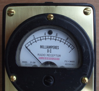
- 1 mA meter
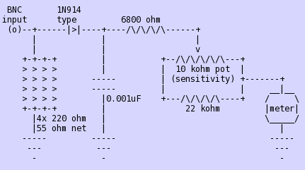
The power rating of the 220Ω resistors defines the power rating of the entire unit, change that as needed. The remaining resistors, capacitor, and milliammeter can be junk box items. The diode is non-critical, a 1N914 / 1N4148 type should be fine. A 1N34 would be better in theory, but most any small signal diode should work.
1N914 datasheetIf you want to use this with higher power, watch the voltage ratings of the diode and capacitor. A 1N914 / 1N4148 diode is only rated to 75 V reverse voltage, pretty close to what you would have at 100 watt input.
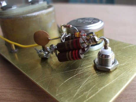
The circuit is built on the back of the panel of a small box.
Why brass instead of aluminum? Brass looks classier.
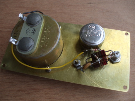
The BNC input is at far right in the views of the interior of the meter face, then the 50Ω load and diode rectifier. Above that is the potentiometer. The meter is at far left.
The close up view of the input circuit shows that the crude construction and junk box parts.
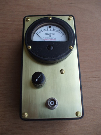
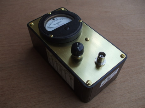
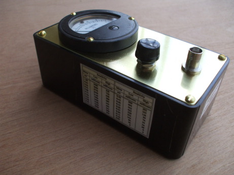
And here is the finished exterior!
Calibration Goal
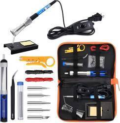
Amazon B06XZ31W3M
Here was my plan: use it in both uncalibrated and calibrated states.
Uncalibrated: If I am working on a transmitter, tweaking a coil or capacitor to get maximum output, I can adjust the potentiometer to move the needle to almost full deflection, so small changes are more visitble. I'm adjusting for maximum power, absolute measurements come later.
Calibrated: Turn the potentiometer all the way to one direction or the other. Then read the meter in milliamps, and look up the corresponding power on a table. Actually, on one of two tables, one for the maximum sensitivity and the other for minimum, or fully clockwise and counter-clockwise.
Calibration Steps
-
Measure the DC resistance between the BNC center pin
and ground.
The diode leads off through a much higher
resistance circuit to ground.
At the high sensitivity setting, with the potentiometer
wiper at the meter end, that branch is from 6800Ω.
At the low sensitivity setting, with the wiper at the
other end, that's 6800Ω in series with
(10kΩ parallel with 22kΩ),
or 13,675Ω.
Both of those are much higher than the net 55ਹ
of the dummy load.
Of course those numbers are approximate, these are handy junk-box resistors.
And of course all of this recklessly conflates DC resistance with RF impedance.
But I'm not trying for NIST-traceable calibration, just something accurate to maybe 5-10%. So, on to the next step: - Connect an adjustable DC power supply, negative to the ground and positive to the BNC center pin. Also connect a DC volt meter across here.
- Turn the potentiometer all the way to one end.
- Adjust the power supply to drive the meter to the 20 different levels on its scale: 0.05 mA, 0.10 mA, 0.15 mA, and so on to full 1.00 mA. Write down the list of meter readings and required input voltages.
- Turn the supply down to 0 V, turn the potentiometer all the way to the other end of its range, and repeat the above step to make a second list.
-
Do the math: P = V2/R
Use the measured resistance for R, and the measured voltage for V. The result is in watts.
Let's say that I really measured precisely 55.0Ω across the BNC connector. And let's say that to get the meter to read 1.00 mA required a voltage of 13.845 V with the potentiometer turned all the way to the low-sensitivity end of its range, and 6.758 V with it turned fully the other way.
13.8452/55 = 3.485164
6.7582/55 = 0.830374
The first row of my table would look like this:Meter
readingPower mA mW, low mW, high 1.00 3485 830 ... - Print your table and put it on the side of the case.
For my collection of junk parts that calibration table worked out as follows:
| Meter reading |
Power | |
| mA | mW, low | mW, high |
| 1.00 | 3480 | 828 |
| 0.95 | 3090 | 736 |
| 0.90 | 2770 | 658 |
| 0.85 | 2430 | 580 |
| 0.80 | 2140 | 507 |
| 0.75 | 1900 | 445 |
| 0.70 | 1660 | 393 |
| 0.65 | 1420 | 341 |
| 0.60 | 1210 | 290 |
| 0.55 | 1030 | 244 |
| Meter reading |
Power | |
| mA | mW, low | mW, high |
| 0.50 | 860 | 202 |
| 0.45 | 695 | 165 |
| 0.40 | 542 | 128 |
| 0.35 | 422 | 99 |
| 0.30 | 320 | 76 |
| 0.25 | 223 | 54 |
| 0.20 | 144 | 34 |
| 0.15 | 86 | 20 |
| 0.10 | 36 | 9 |
| 0.05 | 9 | 2 |